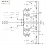
Am I missing something? It is called an fet preamp but it is all bjt.
Maybe he forgot to change the name because I also have the FET schematic
Regards
Juan
Attachments
Maybe he forgot to change the name because I also have the FET schematic
Regards
Juan
Yes I forgot to change the name, nice work Juan.
Regards
PDF for this PCB. Thank You Sir.
I'm going to be honest, I'm not an expert or circuit designer
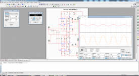
") I only try to do my best way possible I will leave the files here it came out too big but is better because the traces are a bit thicker than what I usually do that is 1.5 mm this are 1.75 to 1.80 mm I have already simulated and it came out 1.5Vp on the output please if some one see an error let me know
I only try to do my best way possible I will leave the files here it came out too big but is better because the traces are a bit thicker than what I usually do that is 1.5 mm this are 1.75 to 1.80 mm I have already simulated and it came out 1.5Vp on the output please if some one see an error let me know Regards
Juan
Attachments
I'm going to be honest, I'm not an expert or circuit designer
Regards
Juan
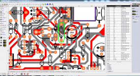
What is size of pcb?
What is size of pcb?
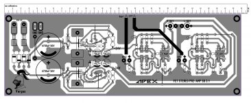
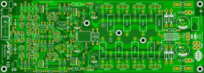
is quite large mister Mile, is 289 mm x 99.5 mm I just make a fast PCB because my layout are sometimes too small I mean on the traces thickness
a common A4 paper sizes is 297 mm x 210 mm maybe I might split the PCB and have separate power supply and preamp separate, you think might be better like that ?
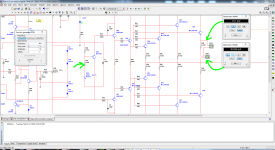
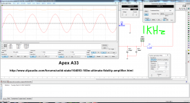
About the A33, today I was checking the simulation of A33 an I have to change only one of the resistors that is controlling the bias R35 from 1K to 470R so now I can get about 30mA = 10 mV reading from one of the emitter resistors,
question, 30mA will be ok to have it set the standby current ?
Regards
Juan
Attachments
Last edited:
is quite large mister Mile, is 289 mm x 99.5 mm I just make a fast PCB because my layout are sometimes too small I mean on the traces thickness
a common A4 paper sizes is 297 mm x 210 mm maybe I might split the PCB and have separate power supply and preamp separate, you think might be better like that ?
About the A33, today I was checking the simulation of A33 an I have to change only one of the resistors that is controlling the bias R35 from 1K to 470R so now I can get about 30mA = 10 mV reading from one of the emitter resistors,
question, 30mA will be ok to have it set the standby current ?
Regards
Juan
30mA is OK
Regards
Board Size
I think if you split it, could it be 140mm X 99.5.? That way it fits on an 8" X 11" (203.2 X 279.4) PCB, and we can get Both boards from 1 PCB.
is quite large mister Mile, is 289 mm x 99.5 mm I just make a fast PCB because my layout are sometimes too small I mean on the traces thickness
a common A4 paper sizes is 297 mm x 210 mm maybe I might split the PCB and have separate power supply and preamp separate, you think might be better like that ?
Regards
Juan
I think if you split it, could it be 140mm X 99.5.? That way it fits on an 8" X 11" (203.2 X 279.4) PCB, and we can get Both boards from 1 PCB.
I think if you split it, could it be 140mm X 99.5.? That way it fits on an 8" X 11" (203.2 X 279.4) PCB, and we can get Both boards from 1 PCB.
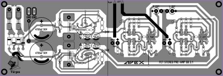
yes it is 140 mm
I trace a line and it measure that 140 mm, I will split this into two PCB later I will post it here the PDF files Regards
Juan
Attachments
Hello last post of the day
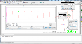
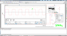
seen now that the bias is set correctly now in simulation from software the I check the square wave to see how it looks now and there is a nice curve on the top at 20KHz and 30KHz, and with sine wave simulation at low volume example 5W of audio "example" the THD is 0.001% of course this is only simulation, I hope all goes smoothly after I order a few PCB to test, I already change R35 to 470R instead of 1K, the trim pot I changed to 1K I'm confidence that this will be a great build for this topology that is unique 
Regards
Juan
seen now that the bias is set correctly now in simulation from software the I check the square wave to see how it looks now and there is a nice curve on the top at 20KHz and 30KHz, and with sine wave simulation at low volume example 5W of audio "example" the THD is 0.001% of course this is only simulation
, I hope all goes smoothly after I order a few PCB to test, I already change R35 to 470R instead of 1K, the trim pot I changed to 1K I'm confidence that this will be a great build for this topology that is unique Regards
Juan
Attachments
Hello last post of the day
seen now that the bias is set correctly now in simulation from software the I check the square wave to see how it looks now and there is a nice curve on the top at 20KHz and 30KHz, and with sine wave simulation at low volume example 5W of audio "example" the THD is 0.001% of course this is only simulation
Regards
Juan
Nice simulation
Regards
Hallo @still4given, the problems with bias and offset are resolved? Thank you.http://ro-en.gsp.ro/index.php?d=e&q=Thank+you!Today I mounted the boards on heatsinks so I could give them a good test. The amp sounds very good but the thermal compensation is not affective. The hotter the amp gets the higher the bias goes. Something need to change there. As I said before, the scale is a little small so the devices are pretty tight together but I would think that would make the comp sensors more affective. The other thing is thebias is very unstable. As the amp heats up the offset can climb pretty high.
good work,when the test pcb ???
Hello sir yes the PCB is completed and by next month I will order just a few for testing let say even if I order new PCB they will be call it "prototype" for now, if all goes well I let you know guys this is my first two layout PCB and it does take more time, like I say I'm gonna risk my own money if all goes wrong it will be me that will have the error and not you guys that is way I did not share the files for now if all goes well, I will share file but please only for personal use
Regards
Juan
Hello guys I just want to show the second board of the AX-14 sorry I made this video to show it to my friends in Puerto Rico and is in Spanish, I was saying that the second board is completed and what I need is the power transistors and a heat sink also that the PCB fit into my hand jejejejeje
https://www.youtube.com/watch?v=BZ-iXuTNuJE&list=UUEV_-UcnVM-o3KnQe6nemTQ
Regards
Juan
https://www.youtube.com/watch?v=BZ-iXuTNuJE&list=UUEV_-UcnVM-o3KnQe6nemTQ
Regards
Juan
if you can sold the pcb it is very good Sir.
Honestly sir, I really do not have that in mind
Regards
Juan
- Home
- Amplifiers
- Solid State
- 100W Ultimate Fidelity Amplifier