Wow. Looks really good.
I'm curious to see how it sounds.
My next project!
regards Olaf
thanks friend!
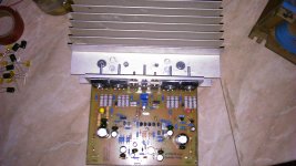
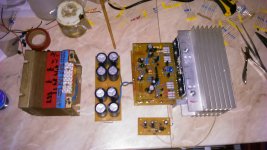
") today i did not had more time so i only mounted output transistors to L-profile and than L-profile to heatsinks:
today i did not had more time so i only mounted output transistors to L-profile and than L-profile to heatsinks:Attachments
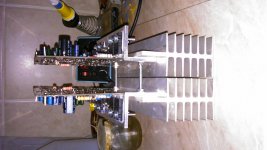
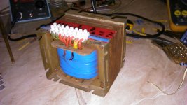
it will be powered by this 400-500VA transformer,cooled by combination of two APEX Fan Controles. there will be in pair temperature controles (one for each heatsink) so the one that "feels" more temperature it will start fan. in paralel to them there will be a fan controle that is being activated by output signal,so i believe that there be a small window for error of activating a fan...
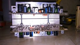
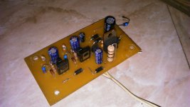
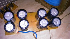
it will have four 4700uF of capacitors per rail,and the speaker protection will be APEX-Zack NE555.
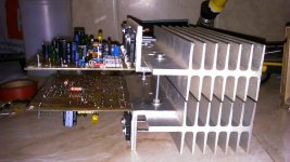
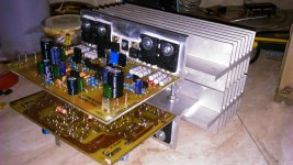
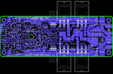
the last picture shows how it should look like in an amplifier casing.
it will have four 4700uF of capacitors per rail,and the speaker protection will be APEX-Zack NE555.
the last picture shows how it should look like in an amplifier casing.
Attachments
both mad,in a positive way off course...
thanks friend!
Nice work, good luck with your A23.
Regards
thanks friend!
Hi, progress looks good! How will you position the fan?
regards
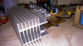
yes i could, but this way it is more practical to me to dis-assemble it if i have to change or fix something on amplifier pcb. also,there allready were some holes on heatsink flange at places where transistors should be...
.
Olaf,cooling fan will be on one side of heatsink group, and the bottom and top of chasing will form a sort of wind tunel for air to flow.
.
Olaf,cooling fan will be on one side of heatsink group, and the bottom and top of chasing will form a sort of wind tunel for air to flow.
although the recording can´t tell you how it really sounds,it can show you that the thing works. i used radio stations...
https://www.youtube.com/watch?v=sEmb_wiHIBA
https://www.youtube.com/watch?v=sEmb_wiHIBA
although the recording can´t tell you how it really sounds,it can show you that the thing works. i used radio stations...
https://www.youtube.com/watch?v=sEmb_wiHIBA
Nice work,
Regards
although the recording can´t tell you how it really sounds,it can show you that the thing works. i used radio stations...
https://www.youtube.com/watch?v=sEmb_wiHIBA
Super. It works. This is the best moment when you know that it sings

regards Olaf

My hat out....... Another PCB dual in line ,
Regards ,Alex

Great layout. Really professional....... Another PCB dual in line ,
Regards ,Alex
regards
I built the A17 based on the layout in post 3551. The only changes I made was to use 500p in place of 470p because I didn't have any on hand. I used NJW0281/0302 for the outputs. I get oscillation when a load is connected. Suggestions welcome.
Thanks, Terry
What is frequency and level of oscillation?
- Home
- Amplifiers
- Solid State
- 100W Ultimate Fidelity Amplifier