Hi,
80W might be possible from your +-30Vdc supply.
a guide for device power is around 2 to 3times output for each half polarity.
This indicates that around 160W to 240W of device power on each rail.
2pair might just about work.
Now do the full SOAR for the temperature and heatsink and smoothing and transformer and load reactance and see if two pair is really enough.
Look for the SOA graph of the output BJT's! If you don't exceed 100mS SOA in case the load has 45...60° phase angle, and graph is derated to ~70°C case temperature (max. ~100°C junction temperature) then you're OK.
For your amplifier (max. ~44Vpp supply, ~60W-RMS on 4 Ohm load, max. ~6...7A output current) two pair of TIP2955/3055 is enough. Even for PA applications!
For your amplifier (max. ~44Vpp supply, ~60W-RMS on 4 Ohm load, max. ~6...7A output current) two pair of TIP2955/3055 is enough. Even for PA applications!
Hi
Welcome and glad to see you've choosen to build your own design.
You say that your aiming for 'near' 100 Watts. I'm glad you say near as your supply is going to be a little low. Assuming you end up with a design that is capable of rail to rail output and asuming your PSU voltage dose not droop much then your already cutting things close.
30V / 1.42 = 21.12Vrms
21.12Vrms / 4R ( load ) = 5.28A
21.12V * 5.28A = 111.5 Wrms
Even a slight drop in voltage of a few volts will bring this figure tumbling down. e.g a 5V drop already gets you down to 75Wrms
This in mind i would try and bump up the PSU by at least a few volts. Anyway about the trannies. According to the data sheet that i will attach below you are allowed 115W each.
Assuming that you build a class A/B thus rendering the bias current dissipation negligable then you will have:-
30V / 4R = 7.5Apk
7.5Apk / 2 ( shared current ) = 3.75Apk @ 30V
The above has to be checked for SAO operation limits.
Again:-
30V / 1.42 = 21.12Vrms
21.12Vrms / 4R = 5.28A
5.28A / 2 ( parallel pair share ) = 2.64A each
21.12Vrms * 2.64A = 55W rms power dissipation across each device. The RMS power can be pretty much considered to be what you are going to get if you drive your amp at max befor distortion.
30V * 3.75 = 112.5 Watts of potential power dissipation accross each device if the amp is abused. design for this level. According to the data sheet you are just about safe at this level. I personally would think that 2 devices are enough as long as you dont plan on driving the amp into hard cliping for extended periods. If you do intend to ensure abuse will not damage things then throw an extra pair in ( or two if you use a flimsy heat sink )
This of course is MY opinion and i apologise in advance for any errors but this is how i usally calc things.
Good luck!
Leigh
Attachments
Hi and thanks for all your replies. Well sorry i forgot to mention this amp will drive a music sub.My calculations i close to yours nitrate as i ended up with 360W total dissipation but let me explain this is in case i have an ideal power supply which will never collapse. Real life calculations for 2 tip 2955 and 2 tip 3055 is less than half of 360W ") D sorry can';t tell the exact figure dunno where is put my papers again must be somewhere in my mess) Well nitrate you sent me datasheet for 2N3055/MJ2955 i know these are 115W am not using them cause i got counterfeits of these being sold here. The TIPs seem safer i've used these successfully elsewhere. So to be on the safe side i'll add another pair of output which means 3 tip2955 and 3 tip3055. Am attaching the schematic here i case you want to have a look and see anything wrong please do report.
D sorry can';t tell the exact figure dunno where is put my papers again must be somewhere in my mess) Well nitrate you sent me datasheet for 2N3055/MJ2955 i know these are 115W am not using them cause i got counterfeits of these being sold here. The TIPs seem safer i've used these successfully elsewhere. So to be on the safe side i'll add another pair of output which means 3 tip2955 and 3 tip3055. Am attaching the schematic here i case you want to have a look and see anything wrong please do report.
Thanks
D sorry can';t tell the exact figure dunno where is put my papers again must be somewhere in my mess) Well nitrate you sent me datasheet for 2N3055/MJ2955 i know these are 115W am not using them cause i got counterfeits of these being sold here. The TIPs seem safer i've used these successfully elsewhere. So to be on the safe side i'll add another pair of output which means 3 tip2955 and 3 tip3055. Am attaching the schematic here i case you want to have a look and see anything wrong please do report.Thanks
Attachments
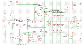
Your amp should work, but I've got some comments if you don't mind!
C7 might cause oscillations, be careful with paralel caps in the FB path. Don't use if the amp is stable without.
For C6 first I'd try 47pF.
R20 could be a the standard 470 Ohm resistor.
About Q5: I'd use BD140 instead. TIP42C has low gain and low Ft, but high Cob.
C13 looks too low for me. I'd use 470pF.
VR1 sholuld be a 470 Ohm resistor in series with a 470/500 Ohm trimmpot. Safety reasons.
Nice circuit anyway! I like too the conventional Lin-topology.
Hi,
I wasnt thinking straight after a boozey sunday afternoon LOL. My calculations are not correct for a class A/B. I was confused after spending most the day fiddling with my latest classA design were the high standing currents must be taken into account. As your going for a class A/B then disregard my previous calcs. The only thing you need to do is check the peak current against the SOA as i previously showed.
Your actual peak dissipation in the trannies is going to be
15v / 1.42 = 10.56Vrms
10.56 / 4R = 2.64A
2.64A * 10.56 = 27.88W
27.88W / 2 ( pair ) = approx 14W of heat dissipation each.
The reason for this is we forget that the closer to the power rails we get the less of a volt drop is seen across the tranny so although current is increasing the power actually falls after the half way point. This is why the likes of classD are so efficient and run cold.
Therefore under normal running i must conclude that the origanal parallel pair will be enough as long as the peak current shared between them is within the SOA for the given predicted temp of the heat sink ect.
I apologise for my errors, its only now i'm at work and sober that i see clearly once more LOL. P.S i like your choice of tip41/2 for drivers, I personally like to use them too, they are very linear.
Leigh
thanks guys
Thanks leigh and andy. Well leigh no worries its mostly whem am in those states that am inspirational bout what i build lol but thats another story all by itself. I'll do the recommended changes you mentionned francis those you are mentionning for C7 and C13 were my initial design goals. I'll do the other mods as well and keep to the original 2 pair of output.
Just one more question guys before i jump into pcb design, regarding dc offset, would you recommend (1) a 100Ohm preset inserted between R1 and R2 with center preset going to Q13?
OR
(2)a series 100ohm preset in series with R20?
I know you will end recommend (1) but what would be wrong in doing (2)?
Thanks
Thanks leigh and andy. Well leigh
no worries its mostly whem am in those states that am inspirational bout what i build lol but thats another story all by itself. I'll do the recommended changes you mentionned francis those you are mentionning for C7 and C13 were my initial design goals. I'll do the other mods as well and keep to the original 2 pair of output. Just one more question guys before i jump into pcb design, regarding dc offset, would you recommend (1) a 100Ohm preset inserted between R1 and R2 with center preset going to Q13?
OR
(2)a series 100ohm preset in series with R20?
I know you will end recommend (1) but what would be wrong in doing (2)?
Thanks
True,
Your speaker can appear to present amost no resistance when being driven in the real world, you have to make allowences for this. Your amp should self bias ( set its own DC level ) due to using a diff pair at the input. If you feel the need to trim this down further then i'd suggest adjusting the base current of Q1 by trimming R5. This will have the cheeky effect of triming your dc offset at the output. altering R20 is not a good idea as this would only result in adjusting the LTP current and should not really effect the offset.
Leigh
Hi
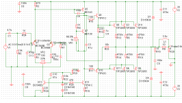
This circuit looks pretty good for the typical diff input, CCS loaded single ended VAS, Darlington EF follower with global feedback type amp. IMO, I would stick with 3 pair of these outputs as they are common and cheap.....usually. I find a little over design in a diy audiophile circuit is a good thing.
According to the datasheet for the TIP42C from On-Semi, the small signal Hfe is only 20. I'm thinking this may be a bit low with a VAS current of ~12mA. The input stage must supply ~0.6mA of base current for this transistor. It appears the input stage bias is only about 0.6mA per leg, which is too low for the MPSA42, and not really enough to drive the TIP42C. Try at least 1mA per leg, perhaps even 5mA per leg. If you do this, don't forget to change the value of R3 to maintain current balance
in the input diff.
Also, as Andy pointed out, the Cob is rather high for a VAS transistor with these circuit conditions. There are better suited transistors out there for this function. However, I don't see a problem with them used as drivers, other than they are kind of slow. There are probably better suited transistors out there for this purpose as well but as we all know, you have to use what you have available.
Just an after thought, a discrete Darlington VAS circuit might be better if you use such a large (relatively) transistor as the VAS.
Re: thanks guys
OK, but I can't see any reason to use 47pF as C13. And if your amp will have bad squarewave response or suffering from oscillation don't forget to do something around C7.
MPSA42s are not rellay suitable here as LTP BJT's. Let's use BC546B! Luckily cheap and available.
If I were you I'd bethought about adding an output-stage protection.
At least add rail fuses on the amplifier PCB!
zeus_threat said:I'll do the recommended changes you mentionned francis those you are mentionning for C7 and C13 were my initial design goals. I'll do the other mods as well and keep to the original 2 pair of output.
OK, but I can't see any reason to use 47pF as C13. And if your amp will have bad squarewave response or suffering from oscillation don't forget to do something around C7.
MPSA42s are not rellay suitable here as LTP BJT's. Let's use BC546B! Luckily cheap and available.
If I were you I'd bethought about adding an output-stage protection.
At least add rail fuses on the amplifier PCB!
CBS240 said:
Just an after thought, a discrete Darlington VAS circuit might be better if you use such a large (relatively) transistor as the VAS.
Nnnnooooooooooo.......

A Darlington pair is with the collectors connected together - that's bad becuse of feedback via Cob.
You buffer the VAS transistor with an emitter follower which has its collector connected to ground.
G.Kleinschmidt said:
Nnnnooooooooooo.......
A Darlington pair is with the collectors connected together - that's bad becuse of feedback via Cob.
You buffer the VAS transistor with an emitter follower which has its collector connected to ground.
Yesssss you are correct. Emitter follower buffer with it's collector to gnd is what I was thinking of, just got out of bed
 , my bad.... R3 would then have 2 diode drops across it intsead of 1.
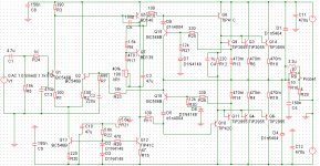
Thanks for all your input updated version attached. Well i could buffer the VAS but am still thinking about it. I've use BC546 for simulation only 2N5551 will be used in the final amp. Any further comments are welcome. By the way the power dissipation was calculated with a phase angle of 45deg. Even though 3 pairs is overkill i'll stick to 3
Your circuit looks better now!
Anyway as I recommended a resistor in series with the bias adjusting trimmpot in the Vbe multiplier circuit would be a good idea for safety reasons (560 Ohm resistor + 500 (470) Ohm trimmpot).
For better offset I'd increase R23 to 15k (16k would be the best choice), then increase R7 to ~820 Ohm. I'd use 220uF elko for C2.
I don't think VR2 is needed. With matched Q1/Q2 you will get max. 10mV DC offset on the output terminal. AOn the margin VR2 could effect serious failure when trimmpot is bad.
Thanks andy added series resistor with vbe preset. I've also added a VI limiting network for safety and other amendments. Any other comments are welcome guys thanks.
would it be better to replace the TIPs with BD139/140 are the SOA of these transistors high enough for the job or better i keep the TIPs?
would it be better to replace the TIPs with BD139/140 are the SOA of these transistors high enough for the job or better i keep the TIPs?
Attachments
- Status
- This old topic is closed. If you want to reopen this topic, contact a moderator using the "Report Post" button.
- Home
- Amplifiers
- Solid State
- 100W peak 4Ohm