The TDA7293-4 has 3db more gain than 3886. You get slightly lower phase margine if you design with3886 model. You can also model with linear elements, voltage controled current source with shunt resistor to fix the DC gain and a capacitor to fix the gain 80db @1Khz and a unity gain buffer. For stability it says closed loop gain 30db, so to use it instead of 26db for 3886.I would appreciate if someone can double check my calculations above, thanks!
Also, is there tda7293 sim model at all?
I wonder if the solution @HAYK offered will work for that chip?

No, not that I'm aware of, that is. In general 7293/94 are in the LM3886 ballpark with regard to general open-loop gain/phase characteristic.Also, is there tda7293 sim model at all?
Only 80dB of open-loop gain, absolute minimum required noise gain is 24dB (30dB nominal) and in closed loop with 30dB the frequency response is -3dB down at ~200kHz, all of which can be used to estimate open-loop gain/phase.

Several posts deleted.
@HAYK you are coming to the attention of the Moderation Team far too often lately. As such you can have a little time out from this thread. The calling out other members as you keep doing does you no favours.
Last edited by a moderator:
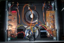
In 2016 I made a 4x4 LM3886 with a single servo, which with the same batch of chips works with minimal stray currents on the R of 0.47 ohm. These currents will give less sense of final power. To avoid this, a C should be added in series with ground to the 1K R in the feedback of each chip.
I also had everything for a 4+4x4+4 with 2 servos and C in series with the 1K R in feedback, therefore pure or surrogate balanced, but I lost the desire...
I also had everything for a 4+4x4+4 with 2 servos and C in series with the 1K R in feedback, therefore pure or surrogate balanced, but I lost the desire...
Attachments
Wouldn’t you need a servo for each individual lm3886 chip? why is there only one per four?In 2016 I made a 4x4 LM3886 with a single servo, which with the same batch of chips works with minimal stray currents on the R of 0.47 ohm. These currents will give less sense of final power. To avoid this, a C should be added in series with ground to the 1K R in the feedback of each chip.
I also had everything for a 4+4x4+4 with 2 servos and C in series with the 1K R in feedback, therefore pure or surrogate balanced, but I lost the desire...
There is really nothing can be done about output dc offset, only current sharing resistors - 0r22 or 0r33 should provide sufficient reduction to where output offset error is insignificant.Also for the paralleled chips in case they "fight eachother" in case of differing offset?
Same with input offset currents, they will never be matched precisely equal, even if differential receiever four 0.1% resistors approach is used.
I consider those engineering compromises that can be minimized but unfortunately cannot be eliminated.
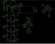
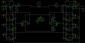
A schematic of your project would be interesting to see.Excited about my latest revision of the LM3886-based amplifier!
- Home
- Amplifiers
- Chip Amps
- Another LM3886 in parallel attempt - this time 4 of them!