Not sure what you are plotting above. Of course, the 3886 will have more NFB at a noise gain of 11 than at a noise gain of 20 or 21. But it will not have more NFB in your configuration than standalone at at gain of 11 because the noise gain is not changed and you haven't introduced extra gain into a global feedback loop which isn't there.
Consider the amp to be unity stable. With low gain, hence high NFB, it has lower distortion and noise. Now, it is not stable at low gain and I add a small capacitor so that at high frequencies, the gain becomes high. Why would you see anything had changed at low frequencies.
I can not force you any conviction, but I am sure the OP is convinced with my arguments.
I can not force you any conviction, but I am sure the OP is convinced with my arguments.
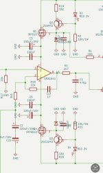
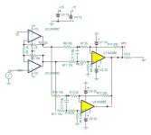
I like simple yet effective solution!If the input is differential only then R2=R3. If single ended, the inverter gain is R3/2k and the non inverter gain is (R2+2k)/2k. This why to pour symmetrical outputs with each, a gain of 6. See VF3 and VF4 graphs.
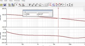
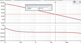
The Amp at low frequencies has 12db higher NFB than with 20k/2k alone.
See the graph bellow.
View attachment 1287114 View attachment 1287115
I would assume OLG at 20k will get some additional dB too!

Have you measured this in practice with a capacitive load? Have a look at the step response as you change the load from 8 Ω || 1 nF to 8 Ω || 1 uF. Also make sure to change the amplitude. You'll want to check both at small-ish signal levels (say a few volt peak-to-peak on the output) and large signals where the output comes within a few volt of clipping.This is a way to reduce the gain of 3886 bellow 3.
Trust me. I've tried many kinds of compensation with the LM3886. Some worked great in the simulator but fell apart in the lab. The LM3886 model doesn't cover anything related to VAS (or VAS CCS) saturation it seems.
Also note that this thread is about four LM3886 in parallel. Not about your investigations of different error correction schemes for the LM3886. You have this thread going already: https://www.diyaudio.com/community/threads/error-corrected-chip-amplifiers-aka-modulus-clone.408330/. I suggest you continue there so we can get back on topic here. You clearly have some interesting ideas and they'll be easier to find in the future if they were in their own thread.
Tom
Ok, now I get what you did. Yes, it reduces gain only at LF. But you still have the problem of thermal feedback from the output stage to the input stage of the 3886 which is what you don't have in a composite amp such as the Neurochrome.Consider the amp to be unity stable. With low gain, hence high NFB, it has lower distortion and noise. Now, it is not stable at low gain and I add a small capacitor so that at high frequencies, the gain becomes high. Why would you see anything had changed at low frequencies.
I can not force you any conviction, but I am sure the OP is convinced with my arguments.
It might be possible to combine your idea of reduced LF gain of the 3886 with the idea of a compsite amp, resulting in yet more NFB at LF.
Temperature is rising in Calgary.Have you measured this in practice with a capacitive load? Have a look at the step response as you change the load from 8 Ω || 1 nF to 8 Ω || 1 uF. Also make sure to change the amplitude. You'll want to check both at small-ish signal levels (say a few volt peak-to-peak on the output) and large signals where the output comes within a few volt of clipping.
Trust me. I've tried many kinds of compensation with the LM3886. Some worked great in the simulator but fell apart in the lab. The LM3886 model doesn't cover anything related to VAS (or VAS CCS) saturation it seems.
Also note that this thread is about four LM3886 in parallel. Not about your investigations of different error correction schemes for the LM3886. You have this thread going already: https://www.diyaudio.com/community/threads/error-corrected-chip-amplifiers-aka-modulus-clone.408330/. I suggest you continue there so we can get back on topic here. You clearly have some interesting ideas and they'll be easier to find in the future if they were in their own thread.
Tom
I'm delighted to report that I've confirmed exceptional measurement results through three days of practical real-world testing with the amplifier.
What's especially noteworthy is the level of resolution—I'm picking up nuances in the music that were previously less apparent. Clarity is another standout feature, with soft yet clear high frequencies and excellent resolution and spaciousness in the midrange.
The low end leans towards the softer side. In comparison to the Modulus-86, the low end is gentler and less pronounced. Modulus has punchier low end.
Testing was done with Emotiva B2+ speakers and Klipsch 12 in subwoofer.
OPA1656 opamps are used as unity follower buffers both in amp and in I/V converter from ES9038 DAC chip.
From that response I'm going to guess that you haven't looked at the performance of the circuit in the lab at loads that would challenge the compensation.Temperature is rising in Calgary.
I've pushed the LM3886 pretty hard into many corners. I know its limitations well and am trying to share this knowledge with you. You're not into that. That's fine. You'll figure it out eventually. You be you.
Tom
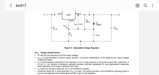
On the contrary, make the supply impedance to be as much resistive and less capacitive possible. LM317/337 can function with less than 1uF output, just load it to 50ma to remain in its low impedance while the lm4562 will be pumping rectified current.
The minimum load needed by these regulators is 10ma, but the lowest output impedance starts above 50ma.
Read bellow about the 1uF.
The minimum load needed by these regulators is 10ma, but the lowest output impedance starts above 50ma.
Read bellow about the 1uF.
Attachments
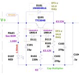
Of those, I'd go with the LM317/337. I get good performance with them. Cap multipliers can be OK, but they don't always respond well to sudden dropouts in the input voltage.I am using simple LM317/LM337 schematics to get +/- 15V.
I can also try capacitance multiplier like Wolverine amp project is using.
Another option could be constant current source/ mosfet regulator
If you're not afraid of SMD components there're also some nice options in the TPS7Axxxx series from Ti.
Tom
Datasheet says 2uVrms typical and 10uVrms max (A-weighted) input referred noise, in the +26dB (20x) test circuit. So, 40uV/200uV output referred.Does a single LM3886 really have 700uV output noise then?
They also state 92.5 dB SNR @1W into 4R (A-weighted), which means 92.5dB below 2V == 47uV.
Therefore, if there is a strong 1/f rise it could be the 20...20k integrated noise reaches several 100 microvolts.
Yes, it is on #92. It is the circuit shown measured. It is not the real value, but to relativise to the 6mv that the lm3886 measures with 20k/1k feedback posted on #94.
The noise of LM4562 is not easy to estimate. As I am asking higher gain 6 instead of 1 it should go higher but the output signal has got higher too which makes lower THD+N.
The noise of LM4562 is not easy to estimate. As I am asking higher gain 6 instead of 1 it should go higher but the output signal has got higher too which makes lower THD+N.
Attachments
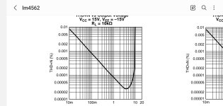
@KSTR, these values are what implemented on the model simulated much higher then real values. Nevertheless it shows how it varies in the circuit. That is the relative value to consider. For now it is 12 times lower than the DS referenced circuit. To remind that the Modulus 286 is only 3 times better.
The main problem to estimate the output noise is lack of information about input current noise. The above values are given with R source of 25 ohm and 600 ohm. The model also doesn't have this data as it ignores the source resistance, 1 ohm or 1 Meg, is the same.Datasheet says 2uVrms typical and 10uVrms max (A-weighted) input referred noise, in the +26dB (20x) test circuit. So, 40uV/200uV output referred.
They also state 92.5 dB SNR @1W into 4R (A-weighted), which means 92.5dB below 2V == 47uV.
Therefore, if there is a strong 1/f rise it could be the 20...20k integrated noise reaches several 100 microvolts.
I will built a noise amplifier with a low noise jfet about 30-40db, and see if I can measure in real with a scope.
- Home
- Amplifiers
- Chip Amps
- Another LM3886 in parallel attempt - this time 4 of them!