
Hello fazildiken,Hello everyone,
Finally finished. Nice work. Beautiful and detailed sound. Thanks to everyone who contributed.
2*25v dc
passive tone control
Nice amplifier. However I saw your 2n3055. The transistors have the same imprint as the one I have bought. You can wash them off with some aceton. Mine were fake ones with a very small dice and the leads . I tested one and crashed at 8A. They should withstand 15A. I bought new ones and they were 5x more expensive than the fakes. Just a warning.
You can revert back to 330pf. Hgher value will only set higher frequency cutoff. I used 1n5 in my built.One question about katiyar's hexfet schematic: the HF input filter: 470 ohms-1.5nF is different of bjt Elvee's version: 470 ohms-330pF ? Why?
Hello Community,
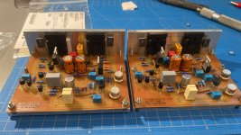
We´ll I'm slower than slow. Anyhow somehow I managed to assembly the myth and the legend.
So result:
1. Rail Voltage - 26V
2. Offset Voltage - between 0.55mV (Both Channels)
3. Quiescent Current - ~160ma (input short)
Components Used:
Q3,Q4 Input BC560C
Q5,Q6 VAS 2N3019
Q8,Q10 Output MJL21194
Q9,Q11 Driver BD140
Q12,Q13 Sensor KSC1845
Listning experience so fare. bass is deep, no rumbling. Mids in total tune, for example cymbals sounds lika a cymbal, all in all easy listening. the sound is excellent, and as everybody say. it is dead silent. Will this amplifier be the end game for me? need more time with this love.
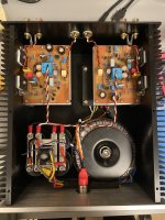
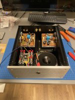
For now everything is lying around like big pie of junk.
I cant have it like this so i have one AL box on hand, missing some stuff to fit everything into the enclosure.
Just a question, how do you more experienced think when you make the final assy of the enclosure.
Like placement of transformers connectors, capacitor banks etc...
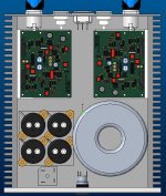
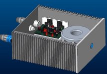
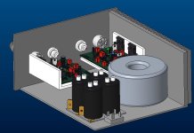
Attached some pictures of my sketch 3D mock up. This is scale 1:1 in 3D Cad. like to work that way make the sketches then assebly everything. usually spare me from surprises in the end.
Best Regards / Sander
We´ll I'm slower than slow. Anyhow somehow I managed to assembly the myth and the legend.
So result:
1. Rail Voltage - 26V
2. Offset Voltage - between 0.55mV (Both Channels)
3. Quiescent Current - ~160ma (input short)
Components Used:
Q3,Q4 Input BC560C
Q5,Q6 VAS 2N3019
Q8,Q10 Output MJL21194
Q9,Q11 Driver BD140
Q12,Q13 Sensor KSC1845
Listning experience so fare. bass is deep, no rumbling. Mids in total tune, for example cymbals sounds lika a cymbal, all in all easy listening. the sound is excellent, and as everybody say. it is dead silent. Will this amplifier be the end game for me? need more time with this love.
For now everything is lying around like big pie of junk.
I cant have it like this so i have one AL box on hand, missing some stuff to fit everything into the enclosure.
Just a question, how do you more experienced think when you make the final assy of the enclosure.
Like placement of transformers connectors, capacitor banks etc...
Attached some pictures of my sketch 3D mock up. This is scale 1:1 in 3D Cad. like to work that way make the sketches then assebly everything. usually spare me from surprises in the end.
Best Regards / Sander
Attachments
@Msander68 no worries I am slower than you are. Your build idea looks very good.
You need to have space for two more things
1) soft start for the TOROID if it’s above 200VA
2) DC protection board for speakers just for safety
3) Something that caught my eye was the XT60 connectors on the board. Interesting choice, only other place I have seen them used in an audio amplifier is Kinky(I) Studio amps.
Other wise only in RC stuff 😊
I think the best placement (re: jpg 1) would be speakons on the right (top/bottom), inputs just right of center (also top/bottom), and IEC power inlet to the far right. Run it’s twisted pair above the right side output transistors. Run the input twisted pairs together from the jacks to the left side board, then one pair between boards. That will minimize any loop formed by the input grounds, and get the radiation source away from it. In the middle of it is the worst place for it to go, making a large one turn air core transformer. Visual symmetry is pretty, but often a bad idea.
Mr Msander68
Congratulations on your build and its excellent performance.I think it will be better to place Toroidal transformer symmetrically in the center of the cabinet but seeing the small size of the cabinet it could be difficult. IEC connector should be away from the input jack to avoid hum. Is this a all aluminium Class A chassis with pre drilled holes for input and output connectors and IEC connector?.
You should put heatsink on VAS transistors as they will get quite hot.
I am curious to know how could you achieve very low offset of 0.55mV. I could not achieve less than 1.5mV in my prototype boards and final stereo boards even with very close matching of transistors and resistors. I think you are the first to achieve such a low offset.
Best wishes for your build.
I know very little, still your design seems very appealing to me. i think u may benefit from using termal paste between the aluminium mounting and the actual heatsink, to make the thermal impedance jump as little as possible so more heat is transfered.
Regards!
Regards!
Super, big thanks to aditya, wg_ski, katiyar
got exactly the response I was looking for... Ok so I will go back to the 3D cad and present some update somewhat later this week
low offset comes from matching transistors and resistors. I tried different approaches of matching the BJT. In the end it was Ian Fritz method with somewhat modified circuit. Bear in mind, this takes time, lots of time. actually quit boring as well.
Brgds / Sander
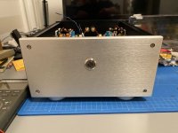
From ears to loaf.
Well it has been a pleasure but what a journey.
Well final figures when everything fitted.
1. Rail Voltage - 25V
2. Offset Voltage - between 0.55mV (Both Channels)
3. Quiescent Current - ~160ma (input short)
Sound. Astonishing, just do it
Would I do it again = Yes
Price wise it is a cheap amplifier compared to other more exotic alternatives here at DIY audio. For the sound. Well read all other posts.
Others. Well from what I can see there is many flavors available. The challenge when attempting this undertaking for unexpired is to decide bjt or mosfet, Decide what power output What type of circuit pcb to select. There is many options in the this thread.
Or just make your own. For a head start, attached my stuff KiCad files. disclaimer, I think everything is OK the amp is playing so probably correct
And please if you’re doing a PCB or other stuff, please share your stuff with source files, and do not just post pictures on your design. Well frankly do not post at all. No one is interested in your property IP pictures. Sharing is caring. Always remember this.
Thanks for all help. And hat off for Elveedesign.
Brgds / Sander
Well it has been a pleasure but what a journey.
- Read +3000 posts, understand what you read
- Redraw the PCB twice in KiCad First pcb no good, second better. Yes all files attached.
- Create pcb gerber files and route the board on the mill (twice!)
- Purchase all components and assembly
- Put everything on hold 6 months because my lab power supply was broken
 . So build a new one on top of this..
 - Test assembly, all working

- Purchase enclosure and the parts needed. Drill holes in enclosure and do final assembly with everything.
Well final figures when everything fitted.
1. Rail Voltage - 25V
2. Offset Voltage - between 0.55mV (Both Channels)
3. Quiescent Current - ~160ma (input short)
Sound. Astonishing, just do it
Would I do it again = Yes
Price wise it is a cheap amplifier compared to other more exotic alternatives here at DIY audio. For the sound. Well read all other posts.
Others. Well from what I can see there is many flavors available. The challenge when attempting this undertaking for unexpired is to decide bjt or mosfet, Decide what power output What type of circuit pcb to select. There is many options in the this thread.
Or just make your own. For a head start, attached my stuff KiCad files. disclaimer, I think everything is OK the amp is playing so probably correct
And please if you’re doing a PCB or other stuff, please share your stuff with source files, and do not just post pictures on your design. Well frankly do not post at all. No one is interested in your property IP pictures. Sharing is caring. Always remember this.
Thanks for all help. And hat off for Elveedesign.
Brgds / Sander
Attachments
That's exactly the spirit of this thread: bravo!And please if you’re doing a PCB or other stuff, please share your stuff with source files, and do not just post pictures on your design. Well frankly do not post at all. No one is interested in your property IP pictures. Sharing is caring. Always remember this.
And congratulations for your build, it is pico bello
Congratulations Msander68 on your build.
I think this the lowest offset voltage achieved by any builder of Circlophone so far. A lot of effert must have been given by you in matching components to achieve this value. I could not achieve such a low value even with rigourous matching of components in BJT and MOSFET versions.
I think this all aluminium chassis is the perfect chassis for Circlophone to radiate heat.
As per my experience Circlophone is the most stable amplifier whose parameters donot change with time.
Congratulations once again for your nice build.
- Home
- Amplifiers
- Solid State
- ♫♪ My little cheap Circlophone© ♫♪