I am playing music on my main speakers which are Dayton DC-160-8 and Vifa Tweeters, its is plenty.
I just need a Chair now - something like this but little more reclined.
even with a lot of bass guitar, i am seeing only 2 volt drop on the supply, maybe increase my Caps from 4700 x 3 to 8200 x 3 down the road when i finalize the box and other thing

I just need a Chair now - something like this but little more reclined.
even with a lot of bass guitar, i am seeing only 2 volt drop on the supply, maybe increase my Caps from 4700 x 3 to 8200 x 3 down the road when i finalize the box and other thing
The thump at power up/down with a small amplifier like this, is not really a problem - not with conventional loudspeakers or compared to what may happen with much more powerful amplifiers of the usual linear type. A simple approach here is really better than cramming in more capacitors to reduce the pulse at power on/off and much better than adding relays with their erratic contact problems.
Mosfet type solid state relays are far superior as an alternative to regular, solenoid/mechanical contact relays though already covered extensively in other threads. Google Bonsai's Hifisonix website for a complete overview and his professional approach to some projects.
So, what idling voltage and bias current is your power supply actually capable of? You may even find that just boosting capacitance does nothing useful if your transformer is already near its own limits.
Last edited:
In principle, the topology ensures that the C wakes up gracefully, provided both supply rails track half-correctly during startup. No one, except you has ever reported such an issue, yet substantial numbers have been built.Observed a small thump at power on and poweroff is there something i could do to stop it.
I still have to check my speaker protection circuit, this will be having the power on delay for speaker connect.
Could it originate from the source/preamp? If there is a volume pot at the input, does it still thump when it is set to zero? In case you have no volume pot there, try starting the amplifier with its input shorted

Hi Elvee,Could it originate from the source/preamp? If there is a volume pot at the input, does it still thump when it is set to zero? In case you have no volume pot there, try starting the amplifier with its input shorted
Yes Elvee I was informed by Katiyar that it’s a silent turn on turnoff and that is why I was surprised with the observation.
I have turned it on with inputs shorted and still got a thump though it was very light but still noticeable.
What could I have done wrong.
BiPolar electrolytic input cap.
My supply transformer is 16-0-16 and I get a dc of around 22 - 0 - 22 volts dc.
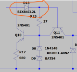
Could it be coz the blocking zeners are 10 volt each.
I have checked the Quiescent current and it’s 150mA and I get around 8.8148e-04 bias current for ccs.
Attached is a recording
Last edited:
Hi Aditya, this is all great what you have built. Effort time cost... etc.
But ever thought about that your layout (PCB) could oscillate ?
You won't get far with frequency counter and your, if I may say so, multimeter.
Honestly between us, an oscilloscope (5MHz), a millivoltmeter and a signal generator should already be
be present with you. A little hint, your frequency counter measures frequencies, not more and not less.
Regardless of the amplitude you give the amplifier.
Judging by the video, you have a DC voltage swing at the output ! Pay attention to the short term diaphragm design of the speaker !!!
And the millivoltmeter should already be an analog one.... not digital. Concerns here your amplifier.
Hi Oscar,You won't get far with frequency counter and your, if I may say so, multimeter.
Thank you pointing out, But I have already accepted it in my post that I am working on it and it’s more painful area
This is just a hobby for which i spend from savings.
I live in a small apartment with parents 14 years younger to you. and my balcony 4’ x 10’ is my work space / study and multipurpose area so till I do not get a space or move my wife’s stuff. It’s going to be limited.
Sorry I didn’t want to rant this but it’s the fact of life.
I do agree with you on this, I will test this power-on swing conditon with a analog meter.And the millivoltmeter should already be an analog one.... not digital. Concerns here your amplifier.
Note: the recording has also the sound of the Switch which is connected to the mains socket and it sort of over laps the speaker sound.Attached is a recording
Mr Elvee,
I have used MPSA42 transistor for CCS in the MOSFET build and have found that a sufficient amount of heat is dissipated across this transistor. Although this setup is stable for a supply voltage of 35v DC in my MOSFET version for a long time. I have an idea to reduce this dissipation and intend to put a 12V zener in series with the CCS circuit to block atleast 12v to reduce dissipation across CCS transistor.
I have observed in the simulation that with this arrangement the CCS current is reduced slightly and quiescent current is reduced by a meagre ~ 1ma, the THD is almost the same.
I need your advice whether this arrangement will be suitable for a higher rail voltage of say 50V DC and would be stable in the longrun.
Thanks
Attachments
Nice build!Mr Elvee,
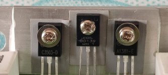
The excellent performance of my previously built MOSFET Circlophone prompted me to build another Circlophone but this time on a proper Class A all aluminium chassis. The last one was built of a salvaged metal cabinet where in I could not fit large heat sinks for output devices. Even with inadequate heat sinks the amplifier is working very well till today.
This time I have checked all components like resistors, capacitors to their actual value and even matched input and VAS transistors on component tester. I have glued input pair transistor BC546B with heat sink compound and bonded them with Araldite. In this build I have used Cascode transistor KSA1381 instead on Zener diode.
I have used soft start circuit to prevent inrush current.
Although this chassis has a provision for Volume Control but I will not use it since putting volume control at the input increases distortion even with a low value of 5K pot.
The build has following parameters;
1. Rail Voltage - 32V
2. Offset Voltage - between 3-4 mV (Both Channels)
3. Quiescent Current - ~164ma (input short)
Components Used
1. Transistor BC546 - CDIL India
2. Transistor 2N5401 - KEC
3. Transistor VAS KSA1381 (ON Semi)
4. Transistor Cascode KSA1381 (ON Semi)
5. Transistor CCS - MPSA42
6. Power Schottky - MBR745 (Taiwan Semiconductor)
7. Signal Schottky - BAT85
8. Output MOSFET - IRFP240
9. Current Sensor Resistor - 1Ohm MOF
10. Other Resistors - MFR
11. Toroidal Transformer - 24-0-24 5 Amp
12. Rail Capacitors - 2 pair of 10000MFD 63V (Samwha)
Both channels are silent with no input.
Again thanks for your excellent schematic design. View attachment 1153590 View attachment 1153592 View attachment 1153599 View attachment 1153601 View attachment 1153602 View attachment 1153603 View attachment 1153608
Can you share details of the soft start board?
Thanks and regards,
Sumesh
Following a request from Aditya, here is an example of an output protection circuit. It is extremely basic, and simply limits the output current (no SOA protection, etc), but you get the idea. You are free to add more bells and whistles of course.
Sorry for the quality of the graphics: importing a schematic into LTspice XVII from earlier versions doesn't work well, but you can see the protection transistors Q14 and Q15:

Sorry for the quality of the graphics: importing a schematic into LTspice XVII from earlier versions doesn't work well, but you can see the protection transistors Q14 and Q15:
If possible, I would try to fit a copper sheet (say 2mm x (50mm)^2) between the output devices and the heat sink. By using a live connection between the drain tab and the copper, that way you can increase the heat conduction of the insulator across the copper and reduce the thermal bottleneck.
(It could also be aluminium. The worst case is where the insulator is connected directly to the device, so all of the heat has to pass through a small area before reaching the heat sink.)
I could not understand your suggestion correctly. You mean to say that put another sheet of aluminium between Transistor and the heat sink. but then there will be one more interface where heat sink paste or any thermal insulator would be required. In such a situation the inter sheet must be smooth and should perfectly fit on the heat sink without any air gap.If possible, I would try to fit a copper sheet (say 2mm x (50mm)^2) between the output devices and the heat sink. By using a live connection between the drain tab and the copper, that way you can increase the heat conduction of the insulator across the copper and reduce the thermal bottleneck.
(It could also be aluminium. The worst case is where the insulator is connected directly to the device, so all of the heat has to pass through a small area before reaching the heat sink.)
Have you practically made such an arrangement and have achieved any benefit out of it?
I have used silicone insulators between transistors and the heat sink. My build is connected to the power supply for more than a week now without any speakers connected to it just for testing heat run issues if any. I am not facing any thermal conduction issues as such.
Thanks for your suggestion. I would definitely consider your suggestion in my next build.
Almost but with a live connection (maybe even soldered) between the transistor and the plate, and multiple plates if the transistors cant be connected together. Kind of like:
(Transistor)
---Solder---
------------Plate------------------
----------Insulator---------------
---------------------heat sink------------------------
The key is that the insulator is by far the worst heat conductor, so its surface area should as big as possible, just with a small sanity check that the additional picofarads of capacitance don't change anything in the circuit.
- Home
- Amplifiers
- Solid State
- ♫♪ My little cheap Circlophone© ♫♪