He's not saving much by using the smoothing circuit over using a discrete regulator. However he builds the amp in a shielded box. You don't think he used his suggested power supply as well?But in post 8,966 there would be no need for a capacitance multiplier as the power drawn by the driver stages is relatively low. For those voltages you could run a normal regulator.
Me too - however he might be refering to audio circuits that have some odd pF value caps dotted about.I think you should explain your theory to some of those dumb people like
Mine have almost all the same power supply 10kuF ,R 0.5 to 1 omh,40kuF
Sounds good. What's your recommendation for transformer? CT or Bridge type? Rectifier choice?
A little about centre tap:
https://www.physics-and-radio-elect...into two types,and full wave bridge rectifier.
https://www.physics-and-radio-elect...into two types,and full wave bridge rectifier.
Bridge type.
A CT transformer for a given voltage has to have two windings so therefore the resistance is higher because you can't get the same number of turns in twice without using thinner wire! Unless the two windings are completely separate then you can parallel them, but the resistance of a single winding might still be (slightly) lower.
A CT transformer for a given voltage has to have two windings so therefore the resistance is higher because you can't get the same number of turns in twice without using thinner wire! Unless the two windings are completely separate then you can parallel them, but the resistance of a single winding might still be (slightly) lower.
Transformers are often offered with 2 separate windings so can be used centre tapped or in parallel or just in series ignoring the centre tap.
The VA rating doesn't change - or does it? RSWW used to do some application notes, one concerned rectification. So say some one has a transformer that has 2 15v windings. 15v can be obtained in 2 ways. Winding in parallel and a full bridge rectifier or 15-0-15 and a 2 diode rectifier. THey reckonned that the 15-0-15 to 15 gives a higher voltage..
The VA rating doesn't change - or does it? RSWW used to do some application notes, one concerned rectification. So say some one has a transformer that has 2 15v windings. 15v can be obtained in 2 ways. Winding in parallel and a full bridge rectifier or 15-0-15 and a 2 diode rectifier. THey reckonned that the 15-0-15 to 15 gives a higher voltage..
"gives a higher voltage"
By one diode drop. And only if the load is small enough to avoid invoking the doubling of available current.
Choke input is the quietest and stiffest rectification method available but I've not seen anyone try it for SS. I've been promising to try it for ages but life keeps getting in the way. And my JLH has the original regulated supply so I'm not motivated to messs= with it
It's convenient to use a toroidal transformer for centre-tapped windings because they are generally wound with a folded pair of wires that inherently form a closely balanced pair with typically low resistance. That's not so easy with an E-I laminated transformer, where the windings are wound individually, one over the other or in sequence, along a divided bobbin. Operator variations also become an issue as they creep into the mix of power supply matters, so the decision to use one form of rectifier or another could also depend on the type and quality of the transformer you have.
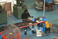
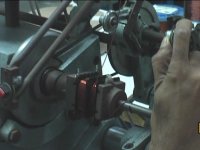
Hi Ian, when the secondary are wound together it is called Bifiliar and the output voltages and current and resistance are exactly the same. I owned and sold majority share to the "workers" in one of my companies that made transformers (in order to retire). All transformers are wound on machines since the very early days and used counters to verify the precise number of windings. The toroidal winding machines (behind the guy that is attaching the fly leads) date out of the early 50s, and the process remains the same still today. EI and R core transformers are wound onto a bobbin, the primary separated from the secondary, then assembled into the E and I core plates loaded into a magazine and alternatively pushing an I core then an e core until filled. The only way to get the exact same characteristics of each secondary is by means of Bifiliar winding, else each secondary would have a different resistance and also inductance.
Attachments

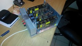
Here is one of the earlier JLH 1969 I converted to split rail and including class H using four SMPS's in order to preserve heat sink cost as well as increase power when required to some 40 watt. The power is switched between a 12-0-12 VDC and 22V-0-22VDC during high peaks. It worked amazingly well and preserved the class A operation at high power while the heat sink remained relatively small. These SMPS costs 1/8 of that of a heat sink for that amount of power.
Attachments
I would like you to think about how you can do this with some block diagram, then we can all discuss this and develop the schematic for this application. It may be useful to many JLH fanatics lurking here, expanding what they already have. Spoon-feeding is too easy. Besides, it remains in line with the JLH thread. No disrespect intended, Veysel.
Thinking out of the box is something that I always encouraged, and I do not want to become the only contributor here.
Thinking out of the box is something that I always encouraged, and I do not want to become the only contributor here.
Last edited:
The rule of thumb on class A for worst case power dissipation in the output transistors is when the amp is static and amplifying nothing. Makes it easy to do the sums. Logical too as when it is amplifying power goes to the loudspeaker. There is also a factor for Class B in respect to sine rms power. Due to inability to test well enough I lost interest in diy amps long ago but that is a lot easier these days. ") It's reawakened the interest. Not yet though - I joined here to do work on speakers.
It's reawakened the interest. Not yet though - I joined here to do work on speakers.
Personally I think mods to the Hood circuit should be part of this thread. Hood published several. Are they worth while - are there better ways etc. The other aspect that often crops up in older designs is suitable transistor replacements. Also Hood could order up matched pairs when he did this amp.
It's reawakened the interest. Not yet though - I joined here to do work on speakers.Personally I think mods to the Hood circuit should be part of this thread. Hood published several. Are they worth while - are there better ways etc. The other aspect that often crops up in older designs is suitable transistor replacements. Also Hood could order up matched pairs when he did this amp.
As thoglette mentioned, a 15-0-15 winding with two diode rectifier would give a slightly higher output voltage, but the point I made is that the winding resistance of each coil is higher, so by using the CT winding you lose regulation on load. CT was really pioneered in valve days when the only rectifier available was a double diode (or rather poor selenium or copper oxide thingys which ususally did not perform well). And in many cases these days a CT transformer is used for the full voltage and then bridge rectified to give dual outputs.
I did make a choke coil for a JLH some time ago. It worked well, but I never made a second channel for stereo. The JLH Class A is ideal because chokes work well for a constant load. With large capacity capacitors available these days, a smaller choke could be beneficially developed. In the valve days there was also a "swinging choke" which allowed a degree of saturation but that seemed never to be able to match the optimum choke (on my calculations) for one designed for a nominal single current. I guess when transformers were always needed for output matching then the extra weight and cost of a choke filter was not in the scheme of things particularly overburdening.
A choke coil too is better for the rectifiers. Keeps the peaks low so while you lose some in the choke resistance you gain some by reducing the voltage loss across the diodes and main transformer. Whether the power supply companies like constant current loading is another matter ... (this option requires the choke to be used before any capacitors)
Last edited:
Hi Nico Ras,
1. detesting the need to switch between the power supplies lower voltage to higher voltage and vice versa, and
2. switching the power supplies fast enough.
Re 1. Switching from the lower voltage current supply to the higher voltage current supply - perhaps this could be accomplished by comparing the voltage of the lower power supply to the voltage of the signal. Then, setting the threshold low enough so that the signal with highest rate of change would still not clip before the switch, thus arguably solving 2.
The disadvantage is that the switching may occur even when not necessary.
Re 1. Switching from the higher voltage current supply to the lower voltage current supply - perhaps a comparator with hysteresis, so that the switching would not occur when the signal varies about the threshold.
Kindest regards,
M
I have been thinking about it, although not "out of the box" because I am not very smart, and I think that there are (at least) two issues:Thinking out of the box is something that I always encouraged, and I do not want to become the only contributor here.
1. detesting the need to switch between the power supplies lower voltage to higher voltage and vice versa, and
2. switching the power supplies fast enough.
Re 1. Switching from the lower voltage current supply to the higher voltage current supply - perhaps this could be accomplished by comparing the voltage of the lower power supply to the voltage of the signal. Then, setting the threshold low enough so that the signal with highest rate of change would still not clip before the switch, thus arguably solving 2.
The disadvantage is that the switching may occur even when not necessary.
Re 1. Switching from the higher voltage current supply to the lower voltage current supply - perhaps a comparator with hysteresis, so that the switching would not occur when the signal varies about the threshold.
Kindest regards,
M
- Home
- Amplifiers
- Solid State
- JLH 10 Watt class A amplifier