It could be used at own advantage as also the woofer excusion under excitation is not symmetrical, in general. The first peak in the impulse response can be damped (low Zout) or not (overshoot) but in reality this is not really a problem because it's very short. It is how it develops in time that leaves the a clear signature on the sound. It really depends on the speaker driver, how it's loaded, its SELF-damping (which often people forget about) and how linearly it beahaves. If you have a very low Zout and the driver has relatively stiff moderately non-linear suspension, such behaviour will be amplified with low Zout (the pluse will take longer to stop!). Not desireable. That is why, having a low Zout is not necessarily an advantage.@45 another interesting point is the effect of the asymmetrical DF on the speaker, where high-voltage and low-current "right side" of the loadline has lower DF compared to the left side.
Last edited:
The 300B is one of the most efficient triodes for Class A1 operation. Class A2 is possible but not great. I have done it several times and the result has always been that distotion is high, whatever driver you wanna use: mosfet source follower, cathode follower or high quality interstage transformer with small power triode. The higher distortion comes from the 300B itself. Some tubes just do not like to be driven in positive grid. The results with 300B have been always the same, especially odd harmonics up to the 11th increase a lot with distortion figures that reach 10% at 10-12W output. I can get 2-3% at about 10W output in A1 with 30W dissipation.Why to use A2 where the grid current is not linear? = because it is the best approach to get the best out of the tube in terms of music and power.
Many amplifier designers make the driver stage able to do A2 to reach over 10 watts instead of heavy blocking and saturating. In the graph above the thd is below 40 db which is good considering he is at 10 watts.
The only difference is that your A2 driver stage is more complex and you have to have some sort of auto-bias monitor to maintain the bias within safe limits (not to destroy the tube).
You really need to make peace with yourself. If more than 1% is too much, how 10% can be good?
What would be a more linear tube for the same application???
Last edited:
I don't see what is different in what you are doing... with a 30W bias, I am just referring to the fact that if you drive it harder the bias point will shift from 70ma to 100ma+ and start A2 operation, a simple cathode follower can do that, the grid current is not that big. Others who implemented a grid current sink with a bias monitor obtained 12 Watts at 1%,
Your figures of 10% at 12 watts point to maybe the unregulated power supply which drops significantly the B+ or a lower anode voltage with higher bias, to get to my figures you need to have 450V across. There are many commercial designs like this.
You have to monitor the current going into the tube and adjust the grid in real time to prevent going over 100ma.
Many people accidentally destroy the 300B tube because of the bias point which shifts in A2
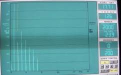
Others who? I don't believe it. In the picture below 10W (9..7W to be precise) class A1. 300B working at 420V/70mA into 4.2K. With very low distortion driver the THD of the amplifier is 3%; With modest amount of H2 cancellation distortion is 1.3%.I don't see what is different in what you are doing... with a 30W bias, I am just referring to the fact that if you drive it harder the bias point will shift from 70ma to 100ma+ and start A2 operation, a simple cathode follower can do that, the grid current is not that big. Others who implemented a grid current sink with a bias monitor obtained 12 Watts at 1%,
And no. B+ was regulated and fine. Bias steady. It's a feature of the 300B. Others tubes like 811A, 807 etc are fine when driven into positive grid.Your figures of 10% at 12 watts point to maybe the unregulated power supply which drops significantly the B+ or a lower anode voltage with higher bias, to get to my figures you need to have 450V across. There are many commercial designs like this.
You have to monitor the current going into the tube and adjust the grid in real time to prevent going over 100ma.
Many people accidentally destroy the 300B tube because of the bias point which shifts in A2
Attachments

Can I ask you an help with this OPT as example?Damping Factor:
How many of you:
1. Have ever measured the inductance of the output transformer secondary?
Note: The output transformer secondary inductance affects the low frequency damping factor, and it affects the LCR resonances of the woofer (open baffle, ported baffle, closed baffle, horn, etc.)
https://sklep.toroidy.pl/en_US/p/TTG-KT88SE-Tube-output-UL-transformer-3kOhm-KT88-300B-SE/566
Primary Inductance Lp = 39,5 H
Total Primary DC Resistance = 109,7 Ω
Total Secondary DC Resistance = 0,7 Ω
Effective Primary Capacitance = 7,6 nF
Turns Ratio (Np:Ns) = 27,39:1 (4Ω) , 19,36:1 (8Ω)
https://positive-feedback.com/Issue1/cjwoodeffect.htmAnd, please, do not mention "The Wood Effect" . . . it will have to be a completely different thread.
I was not aware of it. It would be great to have some impressions about it in a dedicated thread.
Thanks
Roberto
Thanks. When you say low Zout you are talking below 2 Ohm, and high Zout above 4 Ohm? Or more extreme values?If you have a very low Zout and the driver has relatively stiff moderately non-linear suspension, such behaviour will be amplified with low Zout (the pluse will take longer to stop!). Not desireable. That is why, having a low Zout is not necessarily an advantage.
Definitely less than 2R, for example using feedback. 2R is still possible with 300B without doing strange things. However between 3R and 2R not much practical difference.Thanks. When you say low Zout you are talking below 2 Ohm, and high Zout above 4 Ohm? Or more extreme values?
If you're visioning the HF dipping resonace, I suspect more likely high capacitance coupling between two outer primary sections. Is your sectioning using outer primary sections, are they high turn? What is your sectioning order and are there secondaries connected in series during the test?
If you're visioning the HF dipping resonace, I suspect more likely high capacitance coupling between two outer primary sections. Is your sectioning using outer primary sections, are they high turn? What is your sectioning order and are there secondaries connected in series during the test?
This is not a problem, leave the quality of the trafo, it is secondary in this case.
The OT was connected as normal in an amp.
This is only to show the impact of the iron on an OT.
You can do this with other thousands of OT and will find, less or more, the same thing.
And it is compliant with the graphs I sent before with the test on secondary open.
Walter
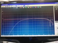
I have always been curious about LF losses without iron, nice to see your results.In attache a test done with a s.e. trafo
THe freq. response with and without iron
It is possible to see that after 1 kHz the iron desn't count nothing
If we coinsider -3dB the F is around 200 Hz
Walter
You mentioned you have this OPT in an amplifier. Have you tested distortion at eg 1kHz with and without the core? I imagine that without the core distortion will be higher, even though frequency response is flat?!
http://wavebourn.com/why_pentodes.html
Where is wavebourn? Let say I am just surprised at your results...
All I can say is that I know it can be done, I built 3 amplifiers based on that company and I know it can deliver the real thing...
In that 300B amp the power supply was 490V the tube was biased both by cathode and grid with a servo, it used 2 or 3 types of feedback ran through a regulated supply of many hundred of negative volts.
@gabdx
@Wavebourn is no more partecipating to this forum.
Based on his posts on this and his old forum, he uses shunt feedback (but he prefers to call it parallel feedback by voltage) from plate to grid on the output tube, plus a current feedback from secondary to the driver to reach even negative Zout and be able to adapt it to the speaker we are using, plus a third feedback that should be from anode of the output tube to the cathode of the driver, but I need to check my notes. He also uses optocouplers with the led across the screen resistors to reduce the input signal and avoid the amp to go into huge distortion.
This way he gets triode-like curves with the efficiency of the pentode (the g1=0 curve brings the anode well below 50V).
It's the same principle of the Baby Huey PP amp.
The other option it's the @Tubelab_com UNSET: purple lines are a KT88 with 20% local feedback anode to grid:

(ref: @SpreadSpectrum https://www.diyaudio.com/community/threads/local-feedback-between-grid-cathode.340415/post-5858884 )
In his last builds @Wavebourn uses PP output transformers. From his description "the second tube has a modulated current" I think it's a single driver tube feeding the grid of one output tube, then the two tubes connected to a common cathode resistor, or a CCS.
The purpose is to have two tubes driving the same current at idle, so using smaller PP output transformers to get the same power avoiding core saturation.
@Wavebourn is no more partecipating to this forum.
Based on his posts on this and his old forum, he uses shunt feedback (but he prefers to call it parallel feedback by voltage) from plate to grid on the output tube, plus a current feedback from secondary to the driver to reach even negative Zout and be able to adapt it to the speaker we are using, plus a third feedback that should be from anode of the output tube to the cathode of the driver, but I need to check my notes. He also uses optocouplers with the led across the screen resistors to reduce the input signal and avoid the amp to go into huge distortion.
This way he gets triode-like curves with the efficiency of the pentode (the g1=0 curve brings the anode well below 50V).
It's the same principle of the Baby Huey PP amp.
The other option it's the @Tubelab_com UNSET: purple lines are a KT88 with 20% local feedback anode to grid:
(ref: @SpreadSpectrum https://www.diyaudio.com/community/threads/local-feedback-between-grid-cathode.340415/post-5858884 )
In his last builds @Wavebourn uses PP output transformers. From his description "the second tube has a modulated current" I think it's a single driver tube feeding the grid of one output tube, then the two tubes connected to a common cathode resistor, or a CCS.
The purpose is to have two tubes driving the same current at idle, so using smaller PP output transformers to get the same power avoiding core saturation.
Hihttps://positive-feedback.com/Issue1/cjwoodeffect.htm
I was not aware of it. It would be great to have some impressions about it in a dedicated thread.
here:
https://www.audioreview.it/news/fase-assoluta-come-riconoscerla.html
The Audioreview numberi is 360 a complete study
there is a beautiful article ( only italian but with traslator will be possible to read) around the absolute phase.
At the end a list of files that can help to understand if someone can hear the phase. It is an experiment can be interesting
Walter
- Home
- Amplifiers
- Tubes / Valves
- Best 300B SE OPT?