Yes it's enough, although you need to consider the secondary DC resistance too and then the core losses to get the full picture across the audio frequency range.
There is not much point is achieving very low Zout with tube amps. Even if one applies feedback to get low Zout, the amplifier will continue to behave like a constant power source. This means that a loudspeker load that drops at much lower mpedance (say, from 8R to 4R) is not desirable, regardless of the damping factor. If load impedance goes up, generally all types of tube amps behave pretty well. Good practice is always get suitable loudspeakers instead of climbing mirrors. Some speakers might even be better with higher Zout amplifiers.
The main reason for having high inductance with low DC resistance in output trnasformers is that it will result in lower distortion.
Last edited:
The consideration around DF must be evaluated also because when it is low the frequency response of the louspeaker vary with his impedance module.
So a choice mus be done. With full range speaker it will be easy and in some case can help; with a bass reflex (p.e.) is more complicate even the efficency is high; the double peak in the region with the energy is great can be a problem.
One of the solution is the use of big and good iron, big wire and high ratio prim/sec, the lost of rms power is not dramatic but the management of louspeaker is better
Walter
Normally the goal is to get the max power possible without other considerations.
Also the best projects doesn't have in mind the variation of the loudsp module because the solutions on output stage would be different around the OT specs
It is my opinion.
Can be a solution to use the FB that is not a crime specially if the frequency response at open loop is wide; 6 or 9 dB of FB also in a s.e. with 300B is not dramatic.
Can I ask you to please elaborate more this point? Leakage inductance rolls off highs where speaker impedance increases, so where an amp with medium-high Zout increases the output, and this flattens the frequency response (up to a point)?It's a reason I like designing my transformer with leakage inductance dominant roll-off, taking advantage of the fact most speaker impedances increase with frequency.
Yes, we get to a point where the driving stage source impedance plays its part. When you get an increasingly higher impedance with frequency, this translates to a higher primary reflected load with frequency. For a SE triode tube stage that would translate to a less steep loadline, limited power output and more second harmonic due to the loadline changing in asymmetry, more voltage being swung to the right section. As for current source stages, higher primary impedance usually gives a higher voltage gain, so that will flatten the frequency response at some point, before asymmetrical clipping occurs.
@45 another interesting point is the effect of the asymmetrical DF on the speaker, where high-voltage and low-current "right side" of the loadline has lower DF compared to the left side.
@waltube thanks, I've seen indeed alot of preferences in SET design (as in every other aspect of human being preferences): maximize power, focus on ratio between harmonics around 1 Wrms, having 2nd harmonic dominant up to 5% THD, minimize THD and IMD, no feedback at all, only local feedback, global feedback, etc...
@50AE thanks again. Do you have a rule of thumb to overdimension the core of the OPT based on the nfb taken from the primary? Something to consider when we buy a OPT and want to try gnfb on SE amps.
I haven't understand well the last post around the Ls (leakege inductance )
The equivalent circuit of a OT are these

the figure 5.10D is at high freq.
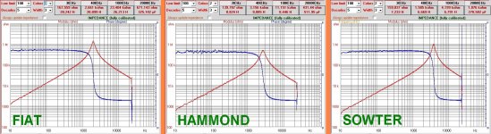
In attach a diagram, already posted some times, where there are the plot of a impedance on some OT with secondary open. All OT for s.e.
There is a peak then, with frequency increase, the Z has an andament typically capacitive ( the C on equivalent circuit), also the phase change at resonance peak.
On the three OT the main aspect we see is that the major issues are on the low frequency where the quality of iron ( and the coils) is more important.
The resonance region is almost the same even the types are much different, between 2 and 3kHz.
But the Z at 10 kHz is high for all types and where the Sowter has the highest value ( but the lowest H, strange? no!)
These test are limited in frequency due the audio card but the range is enough to understand.
The equivalent circuit of a OT are these
the figure 5.10D is at high freq.
In attach a diagram, already posted some times, where there are the plot of a impedance on some OT with secondary open. All OT for s.e.
There is a peak then, with frequency increase, the Z has an andament typically capacitive ( the C on equivalent circuit), also the phase change at resonance peak.
On the three OT the main aspect we see is that the major issues are on the low frequency where the quality of iron ( and the coils) is more important.
The resonance region is almost the same even the types are much different, between 2 and 3kHz.
But the Z at 10 kHz is high for all types and where the Sowter has the highest value ( but the lowest H, strange? no!)
These test are limited in frequency due the audio card but the range is enough to understand.
Attachments
@50AE thanks again. Do you have a rule of thumb to overdimension the core of the OPT based on the nfb taken from the primary? Something to consider when we buy a OPT and want to try gnfb on SE amps.
I'd say smoothest phase response needed. I'd go for more interleaving, hence more shunt capacitance than non-nfb circuits. Capacitance dominant roll-off will bring a more stable frequency response / load. NFB will lower driving impedance anyway, so that's an additional encouragement for going to more interleaving.
@waltube, the plots you're attaching are depicting a typical unloaded transformer driven by a high impedance response, where the inherent primary inductance resonates in parallel with the shunt capacitance. This resonance Q gets flattened, hence the resonance becomes non-visible when the OPT is loaded and the driving impedance is low.
This resonance will shift dynamically in frequency and amplitude, because the primary inductance changes with core excitation level.
300B is not linear 6 watts at more than 1% thd is very bad and limits the amplifier to tailor-made loudspeakers. 300B is a low gain low Rp, for before feedback existed, and good transformers theory and higher voltage capacitors existed, so that it can operate with low voltages. The 845 with proper transformers is a totally different animal. A PX25 is also higher gain, and way smoother sounding. With better transformers and better technology higher gain and more linear tubes were possible to use.Normally the goal is to get the max power possible without other considerations.
Also the best projects doesn't have in mind the variation of the loudsp module because the solutions on output stage would be different around the OT specs
It is my opinion.
Can be a solution to use the FB that is not a crime specially if the frequency response at open loop is wide; 6 or 9 dB of FB also in a s.e. with 300B is not dramatic.
EL34 is (probably) without even looking far superior in SET, so is EL84 and its variants etc
You cannot reach in the linear region of the 300B without exceeding the dissipation. The proper way to use 300B is to get it to work in class A2. Same with 2A3 tubes.
Waltube is right, it is all to your advantage to use some 10db of FB with 300B, especially with a high quality OT.
ou cannot reach in the linear region of the 300B without exceeding the dissipation. The proper way to use 300B is to get it to work in class A2
Not agree
And in a original WE data sheet there isn't mention on A2 class; never use A2 for 300B and 2A3.
It is a crime against this tube!!!!
")
hahaha, you are scared of using a driver stage that can handle grid current.
Not only they can push A2 well, the sound of a driver that can pull grid current is beneficial when the amplifier clips so you don't saturate the driver with clipping and saturation (which is the worst sound you can obtain).
300B draws significant grid current way before entering class A2
Look at glowinthedarkaudio, the reviewer states that 6l6 types tubes will sound better than 300B (6AR6) (6BG6).
My experience is that I designed a cheap 6BL7 (or 6BX7) PPP which gave me a little less power than my 845, but got a superb sound, true to source SMOOTH sound with all the qualities (3D, sound stage etc) and compression and easiness. I would never go back to a SET/without feedback knowing how speakers dependent they are and how they add texture and color which is missing in the source material.
to 50E
the graph are to show the principal aspect of a OT and the Zs is low impedance and low level.
Then with the equivalent circuit where the load is connected the parasitic capacitor C is there with Ls
I have to find a beautiful graph of a s.s. OT without nucleus; you can see some news.
( I forgot where it is!!!!)
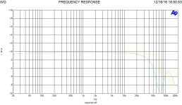
Just for info, in attach a graph with two curves.
The light blue is a normal coil, the yellow is LITZ coil, same iron, same ratio. 4 Vout on 8 ohms, ratio is around 22
Of course different Rdc , Ls and Cs
As you see in the differences are in the high frequency not in the low end ( iron involved) this due the minor parasitic capacitance mainly
the graph are to show the principal aspect of a OT and the Zs is low impedance and low level.
Then with the equivalent circuit where the load is connected the parasitic capacitor C is there with Ls
No, not exactlyThis resonance will shift dynamically in frequency and amplitude, because the primary inductance changes with core excitation level.
I have to find a beautiful graph of a s.s. OT without nucleus; you can see some news.
( I forgot where it is!!!!)
Just for info, in attach a graph with two curves.
The light blue is a normal coil, the yellow is LITZ coil, same iron, same ratio. 4 Vout on 8 ohms, ratio is around 22
Of course different Rdc , Ls and Cs
As you see in the differences are in the high frequency not in the low end ( iron involved) this due the minor parasitic capacitance mainly
Attachments
My (SF driven) EH300B tubes haven't heard of it, so they work happily even in A2 (over about 6.5W) till 10W.never use A2 for 300B

Why to use A2 where the grid current is not linear? = because it is the best approach to get the best out of the tube in terms of music and power.
Many amplifier designers make the driver stage able to do A2 to reach over 10 watts instead of heavy blocking and saturating. In the graph above the thd is below 40 db which is good considering he is at 10 watts.
The only difference is that your A2 driver stage is more complex and you have to have some sort of auto-bias monitor to maintain the bias within safe limits (not to destroy the tube).
In response to this thread, about so many observations, preferences, and opinions:
300B suitability (or pick your favorite amplifier that uses an SE output triode):
For each and every one of you:
How many different models of 300B amplifiers have you heard;
On how many different models of speakers;
And in how many different listening rooms?
All other comments of suitability of a single ended 300B amplifier is: an Opinion, is Hearsay, is Not Observation (can Not stand up in a Court Trial).
Consider that, before you say they are good, bad . . . or mediocre.
Damping Factor:
How many of you:
1. Have ever measured the inductance of the output transformer secondary?
2. Have ever even calculated the secondary inductance of the output transformer . . . by measuring the primary inductance, and then measuring the primary to secondary turns ratio (Inductance goes by the Square of the turns ratio).
Even if the output tube has extremely high plate impedance, rp, the output transformer secondary inductance is part of the damping factor of the amplifier (at low frequencies).
So, if you have not done those measurements or calculations, then please at least think about the implications of connecting that secondary inductance across the loudspeaker woofer (the output transformer secondary inductance is either connected across the woofer;
Or at least it is connected across the series connection of the woofer crossover coil and the woofer voice coil).
Note: The output transformer secondary inductance affects the low frequency damping factor, and it affects the LCR resonances of the woofer (open baffle, ported baffle, closed baffle, horn, etc.)
Think before you judge.
Non Linearity of triode plate impedance, rp (or pick your favorite triode output tube):
In regards to the Varying plate impedance, rp of a 300B, or other triode, consider that to be the main cause of gain change with signal (and it is dominant 2nd harmonic distortion).
But many loudspeakers also have 2nd harmonic distortion (the woofer moves further in one direction than in the other direction).
If you are interested in driver/300B 2nd harmonic cancellation . . .
Then you should also be interested in 300B/Loudspeaker 2nd harmonic distortion cancellation . . .
Just connect the amplifier and loudspeaker +/+ and -/- and listen to the 2nd harmonic distortion;
Then Just re-connect the amplifier and loudspeaker +/- and -/+ and listen to the 2nd harmonic distortion
The system 2nd harmonic distortion is Either partially cancelled, Or adds up to more 2nd harmonic distortion.
If you have not tried this, it is so easy to do. Why not challenge your hearing, and try it?
And, please, do not mention "The Wood Effect" . . . it will have to be a completely different thread.
That is enough of my comments for now.
Last edited:
@50AE how usually toroidal transfomers drop in this scenario, if there's a usually?
I've never got very detailed information from toroidal producers, just that their capacitances are concentrated in a very short part of the windings.
Tororroid cores can be used equally well. You just require less interleaving compared to a single coil EI or double C due to the longer layer length.
- Home
- Amplifiers
- Tubes / Valves
- Best 300B SE OPT?