Have you read the sticky located here---> Recommended highly.How should I add THD measurements for several testpoint in a circuit with LTSpice ? Right now I can only simulate measuring voltages and (mili)amperes. The matching with my actual build is nearly perfect, so it’s time for some more advanced measurements.
Regards, Gerrit
Unfortunately, I think the model contains an error somewhere?Try this 12A6 RCA model:
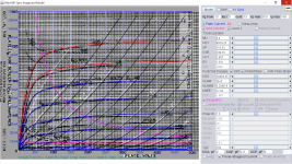
Code:**** 12A6 ****************************************** * Created on 07/25/2022 13:58 using paint_kip.jar * www.dmitrynizh.com/tubeparams_image.htm * Plate Curves image file: 12a6.png * Data source link: <plate curves URL> *---------------------------------------------------------------------------------- .SUBCKT 12A6 P G2 G K ; LTSpice tetrode.asy pinout * .SUBCKT 12A6 P G K G2 ; Koren Pentode Pspice pinout + PARAMS: MU=9.4 KG1=6979.25 KP=110.52 KVB=339.16 VCT=2.657 EX=1.541 KG2=28485.35 KNEE=17.92 KVC=1.801 + KLAM=2E-6 KLAMG=6.204E-8 KNEE2=0.201 KNEX=0.05115 KNK=-0.04158 KNG=0.008585 KNPL=0.625 KNSL=22.22 KNPR=164.07 KNSR=73.58 + CCG=9P CGP=0.3P CCP=9P VGOFF=-1.8 IGA=1.786 IGB=9.5 IGC=0.716 IGEX=0.24 * Vp_MAX=500 Ip_MAX=160 Vg_step=10 Vg_start=20 Vg_count=13 * X_MIN=82 Y_MIN=29 X_SIZE=760 Y_SIZE=607 FSZ_X=1296 FSZ_Y=736 XYGrid=true * Rp=1400 Vg_ac=20 P_max=7.5 Vg_qui=-40 Vp_qui=300 * showLoadLine=n showIp=y isDHP=n isPP=n isAsymPP=n isUL=n showDissipLimit=y * showIg1=y isInputSnapped=y addLocalNFB=n * XYProjections=n harmonicPlot=y dissipPlot=n * UL=0.43 EG2=250 gridLevel2=y addKink=y isTanhKnee=y advSigmoid=n *---------------------------------------------------------------------------------- RE1 7 0 1G ; DUMMY SO NODE 7 HAS 2 CONNECTIONS E1 7 0 VALUE= ; E1 BREAKS UP LONG EQUATION FOR G1. +{V(G2,K)/KP*LOG(1+EXP((1/MU+(VCT+V(G,K))/SQRT(KVB+V(G2,K)*V(G2,K)))*KP))} RE2 6 0 1G ; DUMMY SO NODE 6 HAS 2 CONNECTIONS E2 6 0 VALUE={(PWR(V(7),EX)+PWRS(V(7),EX))} ; Kg1 times KIT current RE21 21 0 1 E21 21 0 VALUE={V(6)/KG1*ATAN((V(P,K)+KNEX)/KNEE)*TANH(V(P,K)/KNEE2)} ; Ip with knee but no slope and no kink RE22 22 0 1 ; E22: kink curr deviation for plate E22 22 0 VALUE={V(21)*LIMIT(KNK-V(G,K)*KNG,0,0.3)*(-ATAN((V(P,K)-KNPL)/KNSL)+ATAN((V(P,K)-KNPR)/KNSR))} G1 P K VALUE={V(21)*(1+KLAMG*V(P,K))+KLAM*V(P,K) + V(22)} * Alexander Gurskii screen current, see audioXpress 2/2011, with slope and kink added RE43 43 K 1G ; Dummy E43 43 G2 VALUE={0} ; Dummy G2 43 K VALUE={V(6)/KG2*(KVC-ATAN((V(P,K)+KNEX)/KNEE)*TANH(V(P,K)/KNEE2))/(1+KLAMG*V(P,K))-V(22)} RCP P K 1G ; FOR CONVERGENCE C1 K G {CCG} ; CATHODE-GRID 1 C2 G P {CGP} ; GRID 1-PLATE C3 K P {CCP} ; CATHODE-PLATE RE23 G 0 1G GG G K VALUE={(IGA+IGB/(IGC+V(P,K)))*(MU/KG1)* +(PWR(V(G,K)-VGOFF,IGEX)+PWRS(V(G,K)-VGOFF,IGEX))} .ENDS *$
It takes forever to simulate a transient response in LTSpice and in the end I get a bogus result.
DC analysis works fine, but AC doesn't
Last edited:
Thanks, I had another look at it, and the model seems to be very picky when the signal is clipped even a little bit.You can try these options:
.option noopiter
.options GminSteps=0
.options SrcSteps=1000
Here is revised12a6 RCA model as previous model draws too much grid1 current, hence VGOFF is adjusted to 0V from -1.8V and grid current scale readjusted. Attached shown is grid current drawn just slightly over driven, that is normal behaviors I believe.
Please try again:
Please try again:
Code:
**** 12A6 ******************************************
* Created on 08/05/2022 01:37 using paint_kip.jar
* www.dmitrynizh.com/tubeparams_image.htm
* Plate Curves image file: 12a6.png
* Data source link: <plate curves URL>
*----------------------------------------------------------------------------------
.SUBCKT 12A6 P G2 G K ; LTSpice tetrode.asy pinout
* .SUBCKT 12A6 P G K G2 ; Koren Pentode Pspice pinout
+ PARAMS: MU=9.4 KG1=6979.25 KP=110.52 KVB=339.16 VCT=2.657 EX=1.541 KG2=28485.35 KNEE=17.92 KVC=1.801
+ KLAM=2E-6 KLAMG=6.204E-8 KNEE2=0.201 KNEX=0.05115  KNK=-0.04158 KNG=0.008585 KNPL=0.625 KNSL=22.22 KNPR=164.07 KNSR=73.58
+ CCG=9P CGP=0.3P CCP=9P VGOFF=0 IGA=2.072 IGB=8.55 IGC=1.375 IGEX=0.1992
* Vp_MAX=500 Ip_MAX=160 Vg_step=5 Vg_start=10 Vg_count=13
* X_MIN=82 Y_MIN=28 X_SIZE=760 Y_SIZE=608 FSZ_X=1296 FSZ_Y=736 XYGrid=true
* Rp=1400 Vg_ac=20 P_max=7.5 Vg_qui=-20 Vp_qui=300
* showLoadLine=n showIp=y isDHP=n isPP=n isAsymPP=n isUL=n showDissipLimit=y
* showIg1=y isInputSnapped=y addLocalNFB=n
* XYProjections=n harmonicPlot=y dissipPlot=n
* UL=0.43 EG2=250 gridLevel2=y addKink=y isTanhKnee=y advSigmoid=n
*----------------------------------------------------------------------------------
RE1  7 0  1G    ; DUMMY SO NODE 7 HAS 2 CONNECTIONS
E1   7 0  VALUE=  ; E1 BREAKS UP LONG EQUATION FOR G1.
+{V(G2,K)/KP*LOG(1+EXP((1/MU+(VCT+V(G,K))/SQRT(KVB+V(G2,K)*V(G2,K)))*KP))}
RE2  6 0  1G    ; DUMMY SO NODE 6 HAS 2 CONNECTIONS
E2  6 0  VALUE={(PWR(V(7),EX)+PWRS(V(7),EX))} ; Kg1 times KIT current
RE21 21 0 1
E21  21 0 VALUE={V(6)/KG1*ATAN((V(P,K)+KNEX)/KNEE)*TANH(V(P,K)/KNEE2)} ; Ip with knee but no slope and no kink
RE22 22 0 1 ; E22: kink curr deviation for plate
E22  22 0 VALUE={V(21)*LIMIT(KNK-V(G,K)*KNG,0,0.3)*(-ATAN((V(P,K)-KNPL)/KNSL)+ATAN((V(P,K)-KNPR)/KNSR))}
G1   P  K  VALUE={V(21)*(1+KLAMG*V(P,K))+KLAM*V(P,K) + V(22)}
* Alexander Gurskii screen current, see audioXpress 2/2011, with slope and kink added
RE43 43 K 1G ; Dummy
E43  43 G2 VALUE={0} ; Dummy
G2   43 K  VALUE={V(6)/KG2*(KVC-ATAN((V(P,K)+KNEX)/KNEE)*TANH(V(P,K)/KNEE2))/(1+KLAMG*V(P,K))-V(22)}
RCP  P K  1G     ; FOR CONVERGENCE
C1   K G  {CCG}  ; CATHODE-GRID 1
C2   G P  {CGP}  ; GRID 1-PLATE
C3   K P  {CCP}  ; CATHODE-PLATE
RE23 G 0 1G
GG G K VALUE={(IGA+IGB/(IGC+V(P,K)))*(MU/KG1)*
+(PWR(V(G,K)-VGOFF,IGEX)+PWRS(V(G,K)-VGOFF,IGEX))}
.ENDS
*$
Attachments
Last edited:
Thanks again!Here is revised12a6 RCA model as previous model draws too much grid1 current, hence VGOFF is adjusted to 0V from -1.8V and grid current scale readjusted. Attached shown is grid current drawn just slightly over driven, that is normal behaviors I believe.
Please try again:
Code:**** 12A6 ****************************************** * Created on 08/05/2022 01:37 using paint_kip.jar * www.dmitrynizh.com/tubeparams_image.htm * Plate Curves image file: 12a6.png * Data source link: <plate curves URL> *---------------------------------------------------------------------------------- .SUBCKT 12A6 P G2 G K ; LTSpice tetrode.asy pinout * .SUBCKT 12A6 P G K G2 ; Koren Pentode Pspice pinout + PARAMS: MU=9.4 KG1=6979.25 KP=110.52 KVB=339.16 VCT=2.657 EX=1.541 KG2=28485.35 KNEE=17.92 KVC=1.801 + KLAM=2E-6 KLAMG=6.204E-8 KNEE2=0.201 KNEX=0.05115 KNK=-0.04158 KNG=0.008585 KNPL=0.625 KNSL=22.22 KNPR=164.07 KNSR=73.58 + CCG=9P CGP=0.3P CCP=9P VGOFF=0 IGA=2.072 IGB=8.55 IGC=1.375 IGEX=0.1992 * Vp_MAX=500 Ip_MAX=160 Vg_step=5 Vg_start=10 Vg_count=13 * X_MIN=82 Y_MIN=28 X_SIZE=760 Y_SIZE=608 FSZ_X=1296 FSZ_Y=736 XYGrid=true * Rp=1400 Vg_ac=20 P_max=7.5 Vg_qui=-20 Vp_qui=300 * showLoadLine=n showIp=y isDHP=n isPP=n isAsymPP=n isUL=n showDissipLimit=y * showIg1=y isInputSnapped=y addLocalNFB=n * XYProjections=n harmonicPlot=y dissipPlot=n * UL=0.43 EG2=250 gridLevel2=y addKink=y isTanhKnee=y advSigmoid=n *---------------------------------------------------------------------------------- RE1 7 0 1G ; DUMMY SO NODE 7 HAS 2 CONNECTIONS E1 7 0 VALUE= ; E1 BREAKS UP LONG EQUATION FOR G1. +{V(G2,K)/KP*LOG(1+EXP((1/MU+(VCT+V(G,K))/SQRT(KVB+V(G2,K)*V(G2,K)))*KP))} RE2 6 0 1G ; DUMMY SO NODE 6 HAS 2 CONNECTIONS E2 6 0 VALUE={(PWR(V(7),EX)+PWRS(V(7),EX))} ; Kg1 times KIT current RE21 21 0 1 E21 21 0 VALUE={V(6)/KG1*ATAN((V(P,K)+KNEX)/KNEE)*TANH(V(P,K)/KNEE2)} ; Ip with knee but no slope and no kink RE22 22 0 1 ; E22: kink curr deviation for plate E22 22 0 VALUE={V(21)*LIMIT(KNK-V(G,K)*KNG,0,0.3)*(-ATAN((V(P,K)-KNPL)/KNSL)+ATAN((V(P,K)-KNPR)/KNSR))} G1 P K VALUE={V(21)*(1+KLAMG*V(P,K))+KLAM*V(P,K) + V(22)} * Alexander Gurskii screen current, see audioXpress 2/2011, with slope and kink added RE43 43 K 1G ; Dummy E43 43 G2 VALUE={0} ; Dummy G2 43 K VALUE={V(6)/KG2*(KVC-ATAN((V(P,K)+KNEX)/KNEE)*TANH(V(P,K)/KNEE2))/(1+KLAMG*V(P,K))-V(22)} RCP P K 1G ; FOR CONVERGENCE C1 K G {CCG} ; CATHODE-GRID 1 C2 G P {CGP} ; GRID 1-PLATE C3 K P {CCP} ; CATHODE-PLATE RE23 G 0 1G GG G K VALUE={(IGA+IGB/(IGC+V(P,K)))*(MU/KG1)* +(PWR(V(G,K)-VGOFF,IGEX)+PWRS(V(G,K)-VGOFF,IGEX))} .ENDS *$
I don't see a lot of difference, and that weird clipping behavior is also still there.
It seems to be a quirk in LTSpice with certain models (not only tube related).
With some parts you just have to clip ever so slightly and it won't work it seems?
I have seen this particular behaviour, where the slightest hint of clipping makes the simulation unstable. It's unpredictable, at least in my experience.Thanks again!
I don't see a lot of difference, and that weird clipping behavior is also still there.
It seems to be a quirk in LTSpice with certain models (not only tube related).
With some parts you just have to clip ever so slightly and it won't work it seems?
During clipping grid 1 went into oscillation esp with cap coupled input. If in A2 (direct coupled) mode rather than A1(cap coupled), it's fine. So I want to post here a less complex grid current model (RGI), but less accurate where everything else is not affected.
12a6 RGI grid current model:
12a6 RGI grid current model:
Code:
**** 12A6 ******************************************
* Created on 08/05/2022 21:08 using paint_kip.jar
* www.dmitrynizh.com/tubeparams_image.htm
* Plate Curves image file: 12a6.png
* Data source link: <plate curves URL>
*----------------------------------------------------------------------------------
.SUBCKT 12A6 P G2 G K ; LTSpice tetrode.asy pinout
* .SUBCKT 12A6 P G K G2 ; Koren Pentode Pspice pinout
+ PARAMS: MU=9.4 KG1=6979.25 KP=110.52 KVB=339.16 VCT=2.657 EX=1.541 KG2=23357.99 KNEE=17.92 KVC=1.873
+ KLAM=2E-6 KLAMG=6.204E-8 KNEE2=0.201 KNEX=0.05115  KNK=-0.04158 KNG=0.008585 KNPL=0.625 KNSL=22.22 KNPR=164.07 KNSR=73.58
+ CCG=9P CGP=0.3P CCP=9P RGI=960.0
* Vp_MAX=500 Ip_MAX=160 Vg_step=5 Vg_start=10 Vg_count=13
* X_MIN=82 Y_MIN=28 X_SIZE=760 Y_SIZE=608 FSZ_X=1296 FSZ_Y=736 XYGrid=true
* Rp=1400 Vg_ac=20 P_max=7.5 Vg_qui=-20 Vp_qui=300
* showLoadLine=n showIp=y isDHP=n isPP=n isAsymPP=n isUL=n showDissipLimit=y
* showIg1=y isInputSnapped=y addLocalNFB=n
* XYProjections=n harmonicPlot=y dissipPlot=n
* UL=0.43 EG2=250 gridLevel2=n addKink=y isTanhKnee=y advSigmoid=n
*----------------------------------------------------------------------------------
RE1  7 0  1G    ; DUMMY SO NODE 7 HAS 2 CONNECTIONS
E1   7 0  VALUE=  ; E1 BREAKS UP LONG EQUATION FOR G1.
+{V(G2,K)/KP*LOG(1+EXP((1/MU+(VCT+V(G,K))/SQRT(KVB+V(G2,K)*V(G2,K)))*KP))}
RE2  6 0  1G    ; DUMMY SO NODE 6 HAS 2 CONNECTIONS
E2  6 0  VALUE={(PWR(V(7),EX)+PWRS(V(7),EX))} ; Kg1 times KIT current
RE21 21 0 1
E21  21 0 VALUE={V(6)/KG1*ATAN((V(P,K)+KNEX)/KNEE)*TANH(V(P,K)/KNEE2)} ; Ip with knee but no slope and no kink
RE22 22 0 1 ; E22: kink curr deviation for plate
E22  22 0 VALUE={V(21)*LIMIT(KNK-V(G,K)*KNG,0,0.3)*(-ATAN((V(P,K)-KNPL)/KNSL)+ATAN((V(P,K)-KNPR)/KNSR))}
G1   P  K  VALUE={V(21)*(1+KLAMG*V(P,K))+KLAM*V(P,K) + V(22)}
* Alexander Gurskii screen current, see audioXpress 2/2011, with slope and kink added
RE43 43 K 1G ; Dummy
E43  43 G2 VALUE={0} ; Dummy
G2   43 K  VALUE={V(6)/KG2*(KVC-ATAN((V(P,K)+KNEX)/KNEE)*TANH(V(P,K)/KNEE2))/(1+KLAMG*V(P,K))-V(22)}
RCP  P K  1G     ; FOR CONVERGENCE
C1   K G  {CCG}  ; CATHODE-GRID 1
C2   G P  {CGP}  ; GRID 1-PLATE
C3   K P  {CCP}  ; CATHODE-PLATE
R1   G 5  {RGI}  ; FOR GRID CURRENT
D3   5 K  DX     ; FOR GRID CURRENT }
.MODEL DX D(IS=1N RS=1 CJO=10PF TT=1N)
.ENDS
*$
Last edited:
Thank you so much again for all the effort!!During clipping grid 1 went into oscillation esp with cap coupled input. If in A2 (direct coupled) mode rather than A1(cap coupled), it's fine. So I want to post here a less complex grid current model (RGI), but less accurate where everything else is not affected.
12a6 RGI grid current model:
Code:**** 12A6 ****************************************** * Created on 08/05/2022 21:08 using paint_kip.jar * www.dmitrynizh.com/tubeparams_image.htm * Plate Curves image file: 12a6.png * Data source link: <plate curves URL> *---------------------------------------------------------------------------------- .SUBCKT 12A6 P G2 G K ; LTSpice tetrode.asy pinout * .SUBCKT 12A6 P G K G2 ; Koren Pentode Pspice pinout + PARAMS: MU=9.4 KG1=6979.25 KP=110.52 KVB=339.16 VCT=2.657 EX=1.541 KG2=23357.99 KNEE=17.92 KVC=1.873 + KLAM=2E-6 KLAMG=6.204E-8 KNEE2=0.201 KNEX=0.05115 KNK=-0.04158 KNG=0.008585 KNPL=0.625 KNSL=22.22 KNPR=164.07 KNSR=73.58 + CCG=9P CGP=0.3P CCP=9P RGI=960.0 * Vp_MAX=500 Ip_MAX=160 Vg_step=5 Vg_start=10 Vg_count=13 * X_MIN=82 Y_MIN=28 X_SIZE=760 Y_SIZE=608 FSZ_X=1296 FSZ_Y=736 XYGrid=true * Rp=1400 Vg_ac=20 P_max=7.5 Vg_qui=-20 Vp_qui=300 * showLoadLine=n showIp=y isDHP=n isPP=n isAsymPP=n isUL=n showDissipLimit=y * showIg1=y isInputSnapped=y addLocalNFB=n * XYProjections=n harmonicPlot=y dissipPlot=n * UL=0.43 EG2=250 gridLevel2=n addKink=y isTanhKnee=y advSigmoid=n *---------------------------------------------------------------------------------- RE1 7 0 1G ; DUMMY SO NODE 7 HAS 2 CONNECTIONS E1 7 0 VALUE= ; E1 BREAKS UP LONG EQUATION FOR G1. +{V(G2,K)/KP*LOG(1+EXP((1/MU+(VCT+V(G,K))/SQRT(KVB+V(G2,K)*V(G2,K)))*KP))} RE2 6 0 1G ; DUMMY SO NODE 6 HAS 2 CONNECTIONS E2 6 0 VALUE={(PWR(V(7),EX)+PWRS(V(7),EX))} ; Kg1 times KIT current RE21 21 0 1 E21 21 0 VALUE={V(6)/KG1*ATAN((V(P,K)+KNEX)/KNEE)*TANH(V(P,K)/KNEE2)} ; Ip with knee but no slope and no kink RE22 22 0 1 ; E22: kink curr deviation for plate E22 22 0 VALUE={V(21)*LIMIT(KNK-V(G,K)*KNG,0,0.3)*(-ATAN((V(P,K)-KNPL)/KNSL)+ATAN((V(P,K)-KNPR)/KNSR))} G1 P K VALUE={V(21)*(1+KLAMG*V(P,K))+KLAM*V(P,K) + V(22)} * Alexander Gurskii screen current, see audioXpress 2/2011, with slope and kink added RE43 43 K 1G ; Dummy E43 43 G2 VALUE={0} ; Dummy G2 43 K VALUE={V(6)/KG2*(KVC-ATAN((V(P,K)+KNEX)/KNEE)*TANH(V(P,K)/KNEE2))/(1+KLAMG*V(P,K))-V(22)} RCP P K 1G ; FOR CONVERGENCE C1 K G {CCG} ; CATHODE-GRID 1 C2 G P {CGP} ; GRID 1-PLATE C3 K P {CCP} ; CATHODE-PLATE R1 G 5 {RGI} ; FOR GRID CURRENT D3 5 K DX ; FOR GRID CURRENT } .MODEL DX D(IS=1N RS=1 CJO=10PF TT=1N) .ENDS *$
Will check later, currently on holiday
")
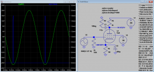
Here is one, based on EICO HF-89, built first, then simulated.I know this thread is really for LTspice tube models, but I was wondering if someone has an LTspice simulation file with models for a push-pull tube power amp? Doesn't matter which tubes, I just want to check something out.
Would save me a lot of time, appreciated!
Jan
Attachments
I will send a PM with a zip fileThanks, that's a nice circuit for me to play with. Could you also post the .asc?
Jan
Edit: my post shows the asc attached, can you see it?
Missing stuff in the archive.Yes I do, sorry I missed it.
Missing triode-w1-ddtransppul , probably a .inc file?
Jan
Jan
Attachments
Attached, just rename it to 6L6.incAlmost! I think I also need .inc c:\Users\jcalv\Google Drive\Electronics\LTSpice\6L6.inc or at least the 6L6.inc .
There are 3 other .inc files which I believe I do not need.
Jan
Attachments
- Home
- Amplifiers
- Tubes / Valves
- Vacuum Tube SPICE Models