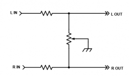
Some early audio equipment did this, but it will tend to reduce the HF response when centered due to high impedance.Can I use a good quality stereo volume control (linear) and just wire one channel in reverse of the other s on o that at center positon both channels have equal settings? Would I have to add any additional components?
Or, use a single linear pot connected between the channels with the wiper grounded and with buildout resistors in each line.
Choose the resistors to work with the pot as you want.
Attachments
Last edited:

... found it, I'll give it a try ... thank you.have a look on my website!
Attachments
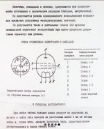
http://www.feerc.ru/rw3xa/tubes/techinfo/TransmittingTubes/gu-72.html
https://frank.pocnet.net/sheets/018/g/GU72.pdf
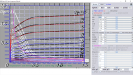
Try this GU-72 Russian model:
https://frank.pocnet.net/sheets/018/g/GU72.pdf
Try this GU-72 Russian model:
Code:
**** GU-72 ******************************************
* Created on 07/24/2022 12:21 using paint_kip.jar
* www.dmitrynizh.com/tubeparams_image.htm
* Plate Curves image file: gu72-p.png
* Data source link: <plate curves URL>
*----------------------------------------------------------------------------------
.SUBCKT GU-72 P G2 G K ; LTSpice tetrode.asy pinout
* .SUBCKT GU-72 P G K G2 ; Koren Pentode Pspice pinout
+ PARAMS: MU=10.04 KG1=23352.68 KP=24.31 KVB=0.648 VCT=15.39 EX=2.229 KG2=69520 KNEE=2.469 KVC=1.617
+ KLAM=8.778E-10 KLAMG=2.33E-6 KNEE2=19.61 KNEX=2654.21  KNK=0.1399 KNG=1.934E-6 KNPL=0.2261 KNSL=0.3432 KNPR=154.24 KNSR=173.04
+ CCG=37P CGP=0.1P CCP=10P VGOFF=-44 IGA=9.03 IGB=0.005243 IGC=542.36 IGEX=0.6588
* Vp_MAX=1500 Ip_MAX=1500 Vg_step=20 Vg_start=15 Vg_count=12
* X_MIN=93 Y_MIN=32 X_SIZE=719 Y_SIZE=544 FSZ_X=1296 FSZ_Y=736 XYGrid=true
* Rp=1400 Vg_ac=20 P_max=84 Vg_qui=-95 Vp_qui=300
* showLoadLine=n showIp=y isDHP=n isPP=n isAsymPP=n isUL=n showDissipLimit=y
* showIg1=y isInputSnapped=y addLocalNFB=n
* XYProjections=n harmonicPlot=y dissipPlot=n
* UL=0.43 EG2=300 gridLevel2=y addKink=y isTanhKnee=y advSigmoid=n
*----------------------------------------------------------------------------------
RE1  7 0  1G    ; DUMMY SO NODE 7 HAS 2 CONNECTIONS
E1   7 0  VALUE=  ; E1 BREAKS UP LONG EQUATION FOR G1.
+{V(G2,K)/KP*LOG(1+EXP((1/MU+(VCT+V(G,K))/SQRT(KVB+V(G2,K)*V(G2,K)))*KP))}
RE2  6 0  1G    ; DUMMY SO NODE 6 HAS 2 CONNECTIONS
E2  6 0  VALUE={(PWR(V(7),EX)+PWRS(V(7),EX))} ; Kg1 times KIT current
RE21 21 0 1
E21  21 0 VALUE={V(6)/KG1*ATAN((V(P,K)+KNEX)/KNEE)*TANH(V(P,K)/KNEE2)} ; Ip with knee but no slope and no kink
RE22 22 0 1 ; E22: kink curr deviation for plate
E22  22 0 VALUE={V(21)*LIMIT(KNK-V(G,K)*KNG,0,0.3)*(-ATAN((V(P,K)-KNPL)/KNSL)+ATAN((V(P,K)-KNPR)/KNSR))}
G1   P  K  VALUE={V(21)*(1+KLAMG*V(P,K))+KLAM*V(P,K) + V(22)}
* Alexander Gurskii screen current, see audioXpress 2/2011, with slope and kink added
RE43 43 K 1G ; Dummy
E43  43 G2 VALUE={0} ; Dummy
G2   43 K  VALUE={V(6)/KG2*(KVC-ATAN((V(P,K)+KNEX)/KNEE)*TANH(V(P,K)/KNEE2))/(1+KLAMG*V(P,K))-V(22)}
RCP  P K  1G     ; FOR CONVERGENCE
C1   K G  {CCG}  ; CATHODE-GRID 1
C2   G P  {CGP}  ; GRID 1-PLATE
C3   K P  {CCP}  ; CATHODE-PLATE
RE23 G 0 1G
GG G K VALUE={(IGA+IGB/(IGC+V(P,K)))*(MU/KG1)*
+(PWR(V(G,K)-VGOFF,IGEX)+PWRS(V(G,K)-VGOFF,IGEX))}
.ENDS
*$
Attachments
Last edited:
Correction: This model corrected wrong scale for Ig1 and VGOFF adjusted:
Code:
**** GU-72 ******************************************
* Created on 07/24/2022 13:03 using paint_kip.jar
* www.dmitrynizh.com/tubeparams_image.htm
* Plate Curves image file: gu72-p.png
* Data source link: <plate curves URL>
*----------------------------------------------------------------------------------
.SUBCKT GU-72 P G2 G K ; LTSpice tetrode.asy pinout
* .SUBCKT GU-72 P G K G2 ; Koren Pentode Pspice pinout
+ PARAMS: MU=10.04 KG1=23352.68 KP=24.31 KVB=0.648 VCT=15.39 EX=2.229 KG2=69520 KNEE=2.469 KVC=1.617
+ KLAM=8.778E-10 KLAMG=2.33E-6 KNEE2=19.61 KNEX=2654.21  KNK=0.1399 KNG=1.934E-6 KNPL=0.2261 KNSL=0.3432 KNPR=154.24 KNSR=173.04
+ CCG=37P CGP=0.1P CCP=10P VGOFF=-3.3 IGA=9.03 IGB=0.005243 IGC=542.36 IGEX=0.922
* Vp_MAX=1500 Ip_MAX=1500 Vg_step=5 Vg_start=15 Vg_count=12
* X_MIN=93 Y_MIN=32 X_SIZE=719 Y_SIZE=544 FSZ_X=1296 FSZ_Y=736 XYGrid=true
* Rp=1400 Vg_ac=20 P_max=84 Vg_qui=-12.5 Vp_qui=300
* showLoadLine=n showIp=y isDHP=n isPP=n isAsymPP=n isUL=n showDissipLimit=y
* showIg1=y isInputSnapped=y addLocalNFB=n
* XYProjections=n harmonicPlot=y dissipPlot=n
* UL=0.43 EG2=300 gridLevel2=y addKink=y isTanhKnee=y advSigmoid=n
*----------------------------------------------------------------------------------
RE1  7 0  1G    ; DUMMY SO NODE 7 HAS 2 CONNECTIONS
E1   7 0  VALUE=  ; E1 BREAKS UP LONG EQUATION FOR G1.
+{V(G2,K)/KP*LOG(1+EXP((1/MU+(VCT+V(G,K))/SQRT(KVB+V(G2,K)*V(G2,K)))*KP))}
RE2  6 0  1G    ; DUMMY SO NODE 6 HAS 2 CONNECTIONS
E2  6 0  VALUE={(PWR(V(7),EX)+PWRS(V(7),EX))} ; Kg1 times KIT current
RE21 21 0 1
E21  21 0 VALUE={V(6)/KG1*ATAN((V(P,K)+KNEX)/KNEE)*TANH(V(P,K)/KNEE2)} ; Ip with knee but no slope and no kink
RE22 22 0 1 ; E22: kink curr deviation for plate
E22  22 0 VALUE={V(21)*LIMIT(KNK-V(G,K)*KNG,0,0.3)*(-ATAN((V(P,K)-KNPL)/KNSL)+ATAN((V(P,K)-KNPR)/KNSR))}
G1   P  K  VALUE={V(21)*(1+KLAMG*V(P,K))+KLAM*V(P,K) + V(22)}
* Alexander Gurskii screen current, see audioXpress 2/2011, with slope and kink added
RE43 43 K 1G ; Dummy
E43  43 G2 VALUE={0} ; Dummy
G2   43 K  VALUE={V(6)/KG2*(KVC-ATAN((V(P,K)+KNEX)/KNEE)*TANH(V(P,K)/KNEE2))/(1+KLAMG*V(P,K))-V(22)}
RCP  P K  1G     ; FOR CONVERGENCE
C1   K G  {CCG}  ; CATHODE-GRID 1
C2   G P  {CGP}  ; GRID 1-PLATE
C3   K P  {CCP}  ; CATHODE-PLATE
RE23 G 0 1G
GG G K VALUE={(IGA+IGB/(IGC+V(P,K)))*(MU/KG1)*
+(PWR(V(G,K)-VGOFF,IGEX)+PWRS(V(G,K)-VGOFF,IGEX))}
.ENDS
*$
Attachments
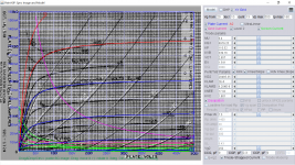
Try this 12A6 RCA model:
Code:
**** 12A6 ******************************************
* Created on 07/25/2022 13:58 using paint_kip.jar
* www.dmitrynizh.com/tubeparams_image.htm
* Plate Curves image file: 12a6.png
* Data source link: <plate curves URL>
*----------------------------------------------------------------------------------
.SUBCKT 12A6 P G2 G K ; LTSpice tetrode.asy pinout
* .SUBCKT 12A6 P G K G2 ; Koren Pentode Pspice pinout
+ PARAMS: MU=9.4 KG1=6979.25 KP=110.52 KVB=339.16 VCT=2.657 EX=1.541 KG2=28485.35 KNEE=17.92 KVC=1.801
+ KLAM=2E-6 KLAMG=6.204E-8 KNEE2=0.201 KNEX=0.05115  KNK=-0.04158 KNG=0.008585 KNPL=0.625 KNSL=22.22 KNPR=164.07 KNSR=73.58
+ CCG=9P CGP=0.3P CCP=9P VGOFF=-1.8 IGA=1.786 IGB=9.5 IGC=0.716 IGEX=0.24
* Vp_MAX=500 Ip_MAX=160 Vg_step=10 Vg_start=20 Vg_count=13
* X_MIN=82 Y_MIN=29 X_SIZE=760 Y_SIZE=607 FSZ_X=1296 FSZ_Y=736 XYGrid=true
* Rp=1400 Vg_ac=20 P_max=7.5 Vg_qui=-40 Vp_qui=300
* showLoadLine=n showIp=y isDHP=n isPP=n isAsymPP=n isUL=n showDissipLimit=y
* showIg1=y isInputSnapped=y addLocalNFB=n
* XYProjections=n harmonicPlot=y dissipPlot=n
* UL=0.43 EG2=250 gridLevel2=y addKink=y isTanhKnee=y advSigmoid=n
*----------------------------------------------------------------------------------
RE1  7 0  1G    ; DUMMY SO NODE 7 HAS 2 CONNECTIONS
E1   7 0  VALUE=  ; E1 BREAKS UP LONG EQUATION FOR G1.
+{V(G2,K)/KP*LOG(1+EXP((1/MU+(VCT+V(G,K))/SQRT(KVB+V(G2,K)*V(G2,K)))*KP))}
RE2  6 0  1G    ; DUMMY SO NODE 6 HAS 2 CONNECTIONS
E2  6 0  VALUE={(PWR(V(7),EX)+PWRS(V(7),EX))} ; Kg1 times KIT current
RE21 21 0 1
E21  21 0 VALUE={V(6)/KG1*ATAN((V(P,K)+KNEX)/KNEE)*TANH(V(P,K)/KNEE2)} ; Ip with knee but no slope and no kink
RE22 22 0 1 ; E22: kink curr deviation for plate
E22  22 0 VALUE={V(21)*LIMIT(KNK-V(G,K)*KNG,0,0.3)*(-ATAN((V(P,K)-KNPL)/KNSL)+ATAN((V(P,K)-KNPR)/KNSR))}
G1   P  K  VALUE={V(21)*(1+KLAMG*V(P,K))+KLAM*V(P,K) + V(22)}
* Alexander Gurskii screen current, see audioXpress 2/2011, with slope and kink added
RE43 43 K 1G ; Dummy
E43  43 G2 VALUE={0} ; Dummy
G2   43 K  VALUE={V(6)/KG2*(KVC-ATAN((V(P,K)+KNEX)/KNEE)*TANH(V(P,K)/KNEE2))/(1+KLAMG*V(P,K))-V(22)}
RCP  P K  1G     ; FOR CONVERGENCE
C1   K G  {CCG}  ; CATHODE-GRID 1
C2   G P  {CGP}  ; GRID 1-PLATE
C3   K P  {CCP}  ; CATHODE-PLATE
RE23 G 0 1G
GG G K VALUE={(IGA+IGB/(IGC+V(P,K)))*(MU/KG1)*
+(PWR(V(G,K)-VGOFF,IGEX)+PWRS(V(G,K)-VGOFF,IGEX))}
.ENDS
*$
Attachments
Last edited:
Thank you so much!! The 14A5 is also an equivalent tube.Try this 12A6 RCA model:
Code:**** 12A6 ****************************************** * Created on 07/25/2022 13:58 using paint_kip.jar * www.dmitrynizh.com/tubeparams_image.htm * Plate Curves image file: 12a6.png * Data source link: <plate curves URL> *---------------------------------------------------------------------------------- .SUBCKT 12A6 P G2 G K ; LTSpice tetrode.asy pinout * .SUBCKT 12A6 P G K G2 ; Koren Pentode Pspice pinout + PARAMS: MU=9.4 KG1=6979.25 KP=110.52 KVB=339.16 VCT=2.657 EX=1.541 KG2=28485.35 KNEE=17.92 KVC=1.801 + KLAM=2E-6 KLAMG=6.204E-8 KNEE2=0.201 KNEX=0.05115 KNK=-0.04158 KNG=0.008585 KNPL=0.625 KNSL=22.22 KNPR=164.07 KNSR=73.58 + CCG=9P CGP=0.3P CCP=9P VGOFF=-1.8 IGA=1.786 IGB=9.5 IGC=0.716 IGEX=0.24 * Vp_MAX=500 Ip_MAX=160 Vg_step=10 Vg_start=20 Vg_count=13 * X_MIN=82 Y_MIN=29 X_SIZE=760 Y_SIZE=607 FSZ_X=1296 FSZ_Y=736 XYGrid=true * Rp=1400 Vg_ac=20 P_max=7.5 Vg_qui=-40 Vp_qui=300 * showLoadLine=n showIp=y isDHP=n isPP=n isAsymPP=n isUL=n showDissipLimit=y * showIg1=y isInputSnapped=y addLocalNFB=n * XYProjections=n harmonicPlot=y dissipPlot=n * UL=0.43 EG2=250 gridLevel2=y addKink=y isTanhKnee=y advSigmoid=n *---------------------------------------------------------------------------------- RE1 7 0 1G ; DUMMY SO NODE 7 HAS 2 CONNECTIONS E1 7 0 VALUE= ; E1 BREAKS UP LONG EQUATION FOR G1. +{V(G2,K)/KP*LOG(1+EXP((1/MU+(VCT+V(G,K))/SQRT(KVB+V(G2,K)*V(G2,K)))*KP))} RE2 6 0 1G ; DUMMY SO NODE 6 HAS 2 CONNECTIONS E2 6 0 VALUE={(PWR(V(7),EX)+PWRS(V(7),EX))} ; Kg1 times KIT current RE21 21 0 1 E21 21 0 VALUE={V(6)/KG1*ATAN((V(P,K)+KNEX)/KNEE)*TANH(V(P,K)/KNEE2)} ; Ip with knee but no slope and no kink RE22 22 0 1 ; E22: kink curr deviation for plate E22 22 0 VALUE={V(21)*LIMIT(KNK-V(G,K)*KNG,0,0.3)*(-ATAN((V(P,K)-KNPL)/KNSL)+ATAN((V(P,K)-KNPR)/KNSR))} G1 P K VALUE={V(21)*(1+KLAMG*V(P,K))+KLAM*V(P,K) + V(22)} * Alexander Gurskii screen current, see audioXpress 2/2011, with slope and kink added RE43 43 K 1G ; Dummy E43 43 G2 VALUE={0} ; Dummy G2 43 K VALUE={V(6)/KG2*(KVC-ATAN((V(P,K)+KNEX)/KNEE)*TANH(V(P,K)/KNEE2))/(1+KLAMG*V(P,K))-V(22)} RCP P K 1G ; FOR CONVERGENCE C1 K G {CCG} ; CATHODE-GRID 1 C2 G P {CGP} ; GRID 1-PLATE C3 K P {CCP} ; CATHODE-PLATE RE23 G 0 1G GG G K VALUE={(IGA+IGB/(IGC+V(P,K)))*(MU/KG1)* +(PWR(V(G,K)-VGOFF,IGEX)+PWRS(V(G,K)-VGOFF,IGEX))} .ENDS *$
Btw, probably already shared in this topic, but what program do you use for matching?
Model Paint Tools: http://www.dmitrynizh.com/tubeparams_image.htm
Go to item 11, download java programs, to run it you need Java Environment (JRE) run time installed on your PC.How should I add THD measurements for several testpoint in a circuit with LTSpice ? Right now I can only simulate measuring voltages and (mili)amperes. The matching with my actual build is nearly perfect, so it’s time for some more advanced measurements.
Regards, Gerrit
Regards, Gerrit
You can use a .fourier statement for each point.How should I add THD measurements for several testpoint in a circuit with LTSpice ? Right now I can only simulate measuring voltages and (mili)amperes. The matching with my actual build is nearly perfect, so it’s time for some more advanced measurements.
Regards, Gerrit
Sorry, I should have given proper answer.Hi,
I hear what you say, but I have no idea how and where to create such a statement. Can you provide a sample? I will search with Google too..
Regards, Gerrit
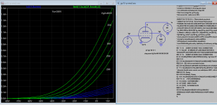
First, click on ".op" button, and enter the .fourier statements as below. Do not forget to "clip" them somewhere in the schematic after clicking OK:
After that just run your simulation, then select View->Spice Error Log
Look at the lats line in blue: Total Harmonic Distortion: 0.46....%Hi,
No problem, thanks for your additional comments.
I will try this tomorrow and see how far I can get. Is it possible to get a overall value like “0.50%”?
Regards, Gerrit
Regards,
Jose
- Home
- Amplifiers
- Tubes / Valves
- Vacuum Tube SPICE Models