See my responses above in red - but everything you asked is flat on the scope. I am willing to resolder, remove, or change either the 22p C7 or 680k resistor if that might be something else to try.
OK, so a flat trace which is what we want. I don't quite know where the peak to peak readout is coming from... maybe the initial transient as you touch the probe tip.
So what is happening is very strange. I would say now that you apply power. That means having just the supplies and the ground return to the PSU connected together with the speaker. So that is 3 wires for the PSU and then the speaker. Nothing else.
Is the speaker ground connection on the amp PCB or is it wired directly back to the PSU? I prefer back to the PSU usually.
The 22pF shouldn't be critical at all, its not like in a set up with a differential input pair and where if it is to large the whole thing will go unstable. I'm just trying that now in the simulation and I can't get it to go unstable at all, even with 10nF fitted there.
I didn't want to spend $5 on two capacitors that were recent revision adds, until I tested and verified the amp was keeper (sorry Mooly).
So I used this one from KEMET:
Multilayer Ceramic Capacitors MLCC - Leaded 200V 22pF C0G 5% LS=5.08mm
C317C220J2G5TA KEMET | Mouser
So I used this one from KEMET:
Multilayer Ceramic Capacitors MLCC - Leaded 200V 22pF C0G 5% LS=5.08mm
C317C220J2G5TA KEMET | Mouser
That cap should be fine... I know some don't like ceramics but its not going to cause a problem.
") my amp was a keeper... it is what I'm listening to right now
my amp was a keeper... it is what I'm listening to right now
Something else is going on with your build as no one as far as I know has had issues like this.
Just a crazy thought but lets prove it OK. If you scope the output of the TL071 (so pin 6) the trace should be clean but sitting at around negative 6 volts from memory. Make sure there is no AC at all on that pin.
Be careful measuring, one slip of the meter would put full supply voltage across the speaker terminals.
my amp was a keeper... it is what I'm listening to right now Something else is going on with your build as no one as far as I know has had issues like this.
Just a crazy thought but lets prove it OK. If you scope the output of the TL071 (so pin 6) the trace should be clean but sitting at around negative 6 volts from memory. Make sure there is no AC at all on that pin.
Be careful measuring, one slip of the meter would put full supply voltage across the speaker terminals.
OK, so a flat trace which is what we want. I don't quite know where the peak to peak readout is coming from... maybe the initial transient as you touch the probe tip.
So what is happening is very strange. I would say now that you apply power. That means having just the supplies and the ground return to the PSU connected together with the speaker. So that is 3 wires for the PSU and then the speaker. Nothing else.
Is the speaker ground connection on the amp PCB or is it wired directly back to the PSU? I prefer back to the PSU usually.
The 22pF shouldn't be critical at all, its not like in a set up with a differential input pair and where if it is to large the whole thing will go unstable. I'm just trying that now in the simulation and I can't get it to go unstable at all, even with 10nF fitted there.
I want to be clear - right now here is my current test wiring:
IEC plug to transformer
CT secondary to PSU board
"+/0/-" from PSU to amp board
GND from amp board directly back to PSU
Speaker + goes to output on amp board
Speaker - goes to GND on board (but I have tried to PSU with same results)
i/p gnd - goes to GND on board thru 10r resistor
RCA input is shorted
so you want me to try it without the i/p gnd connected? and with or without the input shorted?
That cap should be fine... I know some don't like ceramics but its not going to cause a problem.
Something else is going on with your build as no one as far as I know has had issues like this.
Just a crazy thought but lets prove it OK. If you scope the output of the TL071 (so pin 6) the trace should be clean but sitting at around negative 6 volts from memory. Make sure there is no AC at all on that pin.
Be careful measuring, one slip of the meter would put full supply voltage across the speaker terminals.
I get -5.05Vdc on pin 6 and 0.002 Vac on pin 6, so appears to be working correctly. This is with Fluke DMM, my probes are pretty big on the scope.
I want to be clear - right now here is my current test wiring:
IEC plug to transformer

CT secondary to PSU board
+/0/-" from PSU to amp board
GND from amp board directly back to PSU
That makes 2 ground wires. The 0V line in the +/0/- group is ground so where is this other ground running to?
Speaker + goes to output on amp board
Speaker - goes to GND on board (but I have tried to PSU with same results)
those are OK.i/p gnd - goes to GND on board thru 10r resistor
RCA input is shorted
RCA shorted is fine but have you disconnected the wires from the board to the RCA sockets and applied the short at the board itself?
Any chance the sockets are not properly isolated from the chassis? Worth checking with a meter.
The input ground and the 10 ohm. That sounds OK but is unique to the board you are using, however running a single board like this should make all of that unnecessary as there should not be any possible interaction via ground loops. You should just have one single 0V line (which we can call ground) going to the board.
If you try altering the grounds then always check that they still are all electrically connected before switching on as a missing ground could be damaging.
I'm going to have to leave it for tonight but that should hopefully give you something to work with.
I get -5.05Vdc on pin 6 and 0.002 Vac on pin 6, so appears to be working correctly. This is with Fluke DMM, my probes are pretty big on the scope.
The DC voltage sounds fine, the AC part really needs a scope to check. You can always probe the 33k that connects to pin 6 or the 0.1uF cap.
You should see absolutely no signal of any kind on there with no input signal applied.
Let me just take that in...
I did another test and I hope it adds something to the puzzle.
I powered the amp up, exactly how I said my test setup was a couple posts back (with i/p gnd thru 10r and input shorted, no speaker or load connected to the output).
With i/p gnd thru 10r to GND I measure 0.002Vdc and 0.020 Vac on output.
When I disconnect the i/p gnd completely, the voltage on the speakers goes to -27.2Vdc, this is on a PSU providing +/-38.5Vdc.
Not sure what would be pulling it so negative? But obviously why the current draw of the amp goes up.
When I disconnect the i/p gnd completely, the voltage on the speakers goes to -27.2Vdc, this is on a PSU providing +/-38.5Vdc.
Not sure what would be pulling it so negative? But obviously why the current draw of the amp goes up.
this is exactly what Mooly advised against...disconnecting any ground and powering up.
wait a second, which 10 R we are talking about?
I dont have any 10R ground lifter in my PCB.
Only that input side ground and power ground are separated.
Input side ground has a Pin called I/P_GND which should be connected via a wire to the PSU ground on the clean side.
As per APEX (in his DC servo mosfet amplifier thread) , amps with DC servo cant have 10R lifter between input and power ground.
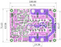
attached is the PCB that you have in your build?
Attachments
Last edited:
The DC voltage sounds fine, the AC part really needs a scope to check. You can always probe the 33k that connects to pin 6 or the 0.1uF cap.
You should see absolutely no signal of any kind on there with no input signal applied.
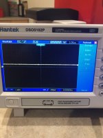
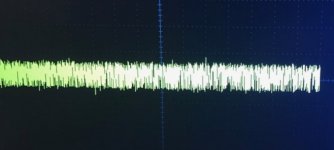
Keep in mind, not 100% sure I'm scoping it correctly. Here is the scope on the 33k resistor, junction of pin 6 of the TL071.
#1 - scope picture
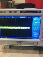
#2 - zoomed in scope
Attachments
Me too, have to go to soccer practice with the kiddos.:
That makes 2 ground wires. The 0V line in the +/0/- group is ground so where is this other ground running to?
I have the "0" from the PSU going to the GND tab on the amp board, also have the speaker negative going to the GND tab on the amp board and originally to get rid of the "noise" I used a 10r resistor in series with the i/p gnd going to that same GND tab on the amp board. So a total of 3 wires going to the Amp board GND tab, with one of those going back to the PSU "0".
RCA shorted is fine but have you disconnected the wires from the board to the RCA sockets and applied the short at the board itself?
yes RCA is disconnected and I have shorted input directly on amp board.
Any chance the sockets are not properly isolated from the chassis? Worth checking with a meter. I will check again, but shouldn't matter, since amp board is not in the case while I'm testing and I still have Hum issue.
The input ground and the 10 ohm. That sounds OK but is unique to the board you are using, however running a single board like this should make all of that unnecessary as there should not be any possible interaction via ground loops. You should just have one single 0V line (which we can call ground) going to the board.
If you try altering the grounds then always check that they still are all electrically connected before switching on as a missing ground could be damaging.
I'm going to have to leave it for tonight but that should hopefully give you something to work with.
That's why I asked earlier, because I knew it would do weird things to the signal. I do have a DBT inline, so the current doesn't go too high. What do you think this could have damaged? I have a few extra TL071 ICs, if you think it is worth swapping it out?this is exactly what Mooly advised against...disconnecting any ground and powering up.
wait a second, which 10 R we are talking about?
I dont have any 10R ground lifter in my PCB.
Only that input side ground and power ground are separated.
Input side ground has a Pin called I/P_GND which should be connected via a wire to the PSU ground on the clean side.
As per APEX (in his DC servo mosfet amplifier thread) , amps with DC servo cant have 10R lifter between input and power ground.
Using a bulb tester should prevent any damage, the FET's are very robust and will easily handle the current the bulb limits things at.
It would be worth repeating that measurement in exactly the same way and recreate what you see in the scope shoot.
Now move from pin 6 to pin 7. Pin 7 should show absolutely no signal of any kind because it is a clean ground. Same for pin 3.
Given that the DC voltages are correct around the opamp suggests it is fine. Fakes or using something other than a TL071 were the big issues but that doesn't seem the case here.
The 0.1uF cap and the 1Meg resistor together with the opamp form an integrator and that means no signal of any kind should be visible on the opamp output. Are those two parts the correct values?
If you interpret this waveform using old fashioned methods (forget the scopes readouts) what do you make the peak to peak voltage to be? Work it out usng the volts/div setting accounting for a divider probe if used.
Keep in mind, not 100% sure I'm scoping it correctly. Here is the scope on the 33k resistor, junction of pin 6 of the TL071.
#1 - scope picture
#2 - zoomed in scope
It would be worth repeating that measurement in exactly the same way and recreate what you see in the scope shoot.
Now move from pin 6 to pin 7. Pin 7 should show absolutely no signal of any kind because it is a clean ground. Same for pin 3.
Given that the DC voltages are correct around the opamp suggests it is fine. Fakes or using something other than a TL071 were the big issues but that doesn't seem the case here.
The 0.1uF cap and the 1Meg resistor together with the opamp form an integrator and that means no signal of any kind should be visible on the opamp output. Are those two parts the correct values?
If you interpret this waveform using old fashioned methods (forget the scopes readouts) what do you make the peak to peak voltage to be? Work it out usng the volts/div setting accounting for a divider probe if used.
Attachments
grounding schemes testing
Spent a couple hours working on this last night. I put the left channel back into the chassis, only after replacing the 0.1uF film capacitor for C8 and checked the 1Meg resistor and both are verified good. I also removed the 10r resistor I have been using with the i/p GND wire and soldered a new 18ga silicone wire to the board, so I could move it around the chassis.
I tried numerous GND schemes and came up with this as the quietest (suggestions welcome)
- positive/zero/negative from PSU to amp board, 2 separated bundles each 3 wires twisted together tightly and removed any extra wire to get to the amp boards
- i/p gnd wire goes directly to the PSU board ground lug
- speaker outputs from amp board to protection board
- speaker negative from PSU lug to protection board
- speaker output from protection board thru 6mH inductor to speaker binding posts
- speaker negative from protection board to speaker negative binding posts
With this wiring scheme I get ~12mVac on the left channel and ~5mVac on right channel (left is audible, with right only audible with ear close to tweeter) I did try taking all wiring grounds to the PSU, but was much noisier, ~24mVac on left and ~10mVac on right.
With this small success, I have put the right channel in now as well and for some reason, the right channel is considerably quieter, but still has a small amount of hum/hiss.
Not sure if this matters, but anytime I put my DMM leads to take measurements during this process (like checking DC or AC on binding posts) or on GNDs, I get some static noise popping coming thru the speaker, with or without music playing.
I also verified that the PSU GNDs I'm using are separate from the chassis/safety earth - not sure if this is normal, as I have never gotten this in-depth with grounding before.
I plan to continue testing the amp and noise and I might try a ground loop breaker at the chassis/safety ground connection and see if that might be a better place to take the some/all of the current PSU GND connections
The protect is powered by AC or DC, in case of DC say +/-12 V , where is its ground connected?
With the new scheme, have you tried powering without protect and other aux circuits?
In one of my amps, I had to power all aux circuits (protect, LED VU meter, etc ) which required a 12vac input, from the same trafo secondary (trafo had dual 12 vac secondaries) , otherwise MBT would light up brightly. I couldn't understand why, it would show short when two separate secondaries are used to power two different circuits.
Not sure if this matters, but anytime I put my DMM leads to take measurements during this process (like checking DC or AC on binding posts) or on GNDs, I get some static noise popping coming thru the speaker, with or without music playing.
That sounds odd. I could understand a single 'click' type noise as the probe made contact if you measured the voltage on a sensitive part of the circuit (such as around the input transistor) but not on things like binding posts and grounds.
There seems to be something unique to your build that is causing problems I'm afraid. Certainly one channel wired up in isolation should be dead silent.
The protect is powered by AC or DC, in case of DC say +/-12 V , where is its ground connected?
With the new scheme, have you tried powering without protect and other aux circuits?
In one of my amps, I had to power all aux circuits (protect, LED VU meter, etc ) which required a 12vac input, from the same trafo secondary (trafo had dual 12 vac secondaries) , otherwise MBT would light up brightly. I couldn't understand why, it would show short when two separate secondaries are used to power two different circuits.
Good question @Prasi - the protection is powered from the +12V regulator on the PSU along with a power-on LED. I did try without using the PSU power and ran the protection from my bench SMPS supply at 13Vdc. Didn't make any difference, so I put it back to maintain protection
I have ordered a 12Vac transformer and going to try that as well and even some other protection boards I have laying around.
That sounds odd. I could understand a single 'click' type noise as the probe made contact if you measured the voltage on a sensitive part of the circuit (such as around the input transistor) but not on things like binding posts and grounds.
There seems to be something unique to your build that is causing problems I'm afraid. Certainly one channel wired up in isolation should be dead silent.
@Mooly - I agree, very odd behavior to have hum/hiss and more odd that it effects both channels, but the left to a much greater degree.
The DMM probe noise is hard to explain, but a static, crackle, popping just at the moment you touch the probes and while fairly minor it concerns me because as you mention, I'm touching non-sensitive parts.
I'm struggling to know what to suggest to you tbh. Given that quite a few have built this amp and that the design itself is proven makes me think that you have to go back to absolute basics with this.
That would mean taking one channel (one PCB) and connecting it up to the power supply with nothing else in the way. Just 3 wires, -,+ and ground. It would have to be made 'safe' to power up and then connect a speaker.
Depending on the outcome of that would dictate where we went next. I know from helping out on the ACA threads that things like an incorrect part that is out by a factor of 10 or 100 can occur and you just don't always spot these kind of things.
A scope check of the amp output into a dummy load and playing a low level 10kHz or similar squarewave might be revealing if there is any instability going on anywhere.
Have a look at the several scope shots here (post #157 onward)
My MOSFET amplifier designed for music.
Thanks!, Here you go sir!
regards
Prasi
Hi Prasi,
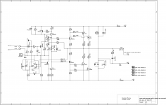
In post # 723 you shared a gerber, unfortunately PCBWAY sees the size
Detected 2 layer board of 91.44x100.08mm (3.6x3.94 inches).
and unfortunately you can't get the lower price :-(
Can this be corrected, please.
- Home
- Amplifiers
- Solid State
- My MOSFET amplifier designed for music