Beautiful work on the single output pcb.
Could we please have the Gerber?
Thank you !
Thanks!, Here you go sir!
")
regards
Prasi
Attachments
-
 stuffing guide_rev2.1_nested fb_single pair.png147.8 KB · Views: 1,212
 -
mooly mosfet amp prasi_rev2.1_fb res_single pair_Cu_Bot.pdf490.2 KB · Views: 427
-
mooly mosfet amp prasi_rev2.1_fb res_single pair_top silk.pdf166.8 KB · Views: 342
-
mooly mosfet amp prasi_rev2.1_fb res_single pair_2018-09-13.zip720.5 KB · Views: 394
Is it a cow or a bear?
I had to scan by browsing history to locate the link from where I had taken it. Make out however you want
.https://www.drawinghowtodraw.com/stepbystepdrawinglessons/wp-content/uploads/2011/09/step-08.png
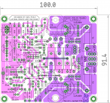
One hint for potential builders while populating the power resistors with Vishay MRA-10 or any other with a diameter of ~8mm.
The middle one (R23) can be raised slightly above the other 2 (R24 &R26), I think 3-5mm would be sufficient. R24 and R26 should be raised above the PCB board by 3-5 mm anyway.
This would ensure proper heat dissipation.
regards
Prasi
The middle one (R23) can be raised slightly above the other 2 (R24 &R26), I think 3-5mm would be sufficient. R24 and R26 should be raised above the PCB board by 3-5 mm anyway.
This would ensure proper heat dissipation.
regards
Prasi
Hello Mooly,
Could you post a delay and DC protect circuit suitable to this amplifier here (35v to 45 v PSU) if you have it? I can make a small pcb which can be mounted on the speaker terminals that also includes the 6uH inductor//10ohm 2W resistor.
For PSU, a single 300VA dual secondary trafo (2x25VAC or 2X 30VAC) along with a single CRC board like Project16's with 22kuF-0.22R-22kuF would suffice the stereo requirements?
This would enable potential builders a complete build package, that they can consider undertaking the project.
These are just my thoughts, you may suggest doing it differently.
regards
Prasi
Attachments
I've no hard copy of the DC protection and delay circuit as I used a combination of Doug Self's switch on delay from the 'Precision Preamp' from 1996 and his DC offset protection circuit from his famous Blameless Class B. Later on I replaced the mechanical relays with discrete solid state versions.
Post #260
Output Relays
Post #273
Output Relays
Post #260
Output Relays
Post #273
Output Relays
Hi Prasi,
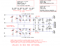
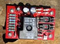
I have just made a speaker protection for the Quasi because I am not ready to connect expensive speaker to transistor amplifier without protection (of course with tube amplifier there is not such a risk because the output transformer block all DC voltage )...
Here is a bad picture and the schematic but it has not been tested yet !
Rgds,
Marc
Attachments
I've no hard copy of the DC protection and delay circuit as I used a combination of Doug Self's switch on delay from the 'Precision Preamp' from 1996 and his DC offset protection circuit from his famous Blameless Class B. Later on I replaced the mechanical relays with discrete solid state versions.
Post #260
Output Relays
Post #273
Output Relays
ok, i will have a look.
Hi Prasi,
I have just made a speaker protection for the Quasi because I am not ready to connect expensive speaker to transistor amplifier without protection (of course with tube amplifier there is not such a risk because the output transformer block all DC voltage )...
Here is a bad picture and the schematic but it has not been tested yet !
Rgds,
Marc
Hello Marc,
this is most helpful.
Lets see, if I can make it so that it can be mounted on speaker terminal.
regards
Prasi
Hi Mooly
Thank you for sharing your amp design
I can’t find any 2N5401 from a reliable source.
Which small transistors would you recommend to replace 5401/5551 while keeping the musicality of your amp.
Thank you
Eric
Are those the only parts you're missing ?
A good friend asked if its possible to make it as a single pair output and reduce the length to less than 100mm to take advantage of low board costs from China.
I gave it a try and here is the result.
It has the same features of the earlier board (caps, resistors, etc, even the logo
regards
Prasi
Mooly, Prasi,
Understand that this project has been ongoing for a long time (a decade!) and lot of developments have been made - apologize in advance for the noob questions
:- What is the power output (in watts) of the amplifier with 2 pairs of outputs and designed for 45V rails (post My MOSFET amplifier designed for music.)
- What is the output with single pair of output devices with lower voltage power rail?
Nominally around 70 wrms developed into 8 ohms on -/+ 45 volt rails.
Parallel output pairs (or using the dual die FET's) will not materially affect this figure but may improve transient peak current delivery into very low impedance loads.
Thank you for clarifying.
Are those the only parts you're missing ?
So far yes, does the thread have a BOM so builder know what to use ?
Ex:
C1 ; Polyester or polypropylene
C2 ; Mica CDE
C3-Cx ; etc...
Fuse value when single output device at +/- 35V (4ohm load)
Thanks
Eric
Last edited:
Hello Eric,
I dont have a BoM.
However I can post the component packages used in an excel sheet, with which some one can make bom.
regards
Prasi
Edit. here you go...These are just component packages. One needs to put part nos.
I dont have a BoM.
However I can post the component packages used in an excel sheet, with which some one can make bom.
regards
Prasi
Edit. here you go...These are just component packages. One needs to put part nos.
Attachments
Last edited:
- Home
- Amplifiers
- Solid State
- My MOSFET amplifier designed for music