Hello Kokane,
This PCB design was just an exercise to keep the blade sharp. Its catching rust these days") .
.
You may get the PCBs manufactured from the gerbers I posted. For 50-60 USD or so, you could get 10 PCBs delivered to you from China. After you fulfil your needs, rest can be rid off with kind permission of Mooly.
If there is sufficient confirmed requirements, I can do the GB as informed to you.
Regards
Prasi
This PCB design was just an exercise to keep the blade sharp. Its catching rust these days
. You may get the PCBs manufactured from the gerbers I posted. For 50-60 USD or so, you could get 10 PCBs delivered to you from China. After you fulfil your needs, rest can be rid off with kind permission of Mooly.
If there is sufficient confirmed requirements, I can do the GB as informed to you.
Regards
Prasi
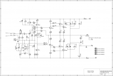
Here is the version with nested FB resistor as suggested by Hugh.
Regards
Prasi
Beautiful work Prasi
The dark line across the pcb in post 699, is that a jumper ?
BR
Eric
Last edited:
Prasi,
Sorry, I guess I did not understand what information was conveyed in our PM's. If the Moderators agree post #702 can be removed, and a GB will not be persued.
Prasi, I will PM you when I decide on my individual requirements, all of course with permission of Mooly.
Best Regards,
Myles
Sorry, I guess I did not understand what information was conveyed in our PM's. If the Moderators agree post #702 can be removed, and a GB will not be persued.
Prasi, I will PM you when I decide on my individual requirements, all of course with permission of Mooly.
Best Regards,
Myles
Why R26?
What is the purpose of R26? It seems to be redundant.
Regards ...
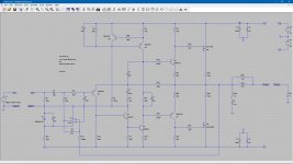
here is the schematic.
What is the purpose of R26? It seems to be redundant.
Regards ...
What is the purpose of R26? It seems to be redundant.
Regards ...
I guess Mooly can answer better, it has a specific reason for inclusion.
Bias Setup.
Comparing simulations of the Mooley to the FX8 with Bimo mods. If you provide sufficient bias, this amplifier should perform just as well as the FX8 with Bimo mods. It should be able to provide very low distortion levels.
What bias current did you setup?
Regards ...
The MMAMFM is more involving to listen to than either the P101 or the MRJ**.
Comparing simulations of the Mooley to the FX8 with Bimo mods. If you provide sufficient bias, this amplifier should perform just as well as the FX8 with Bimo mods. It should be able to provide very low distortion levels.
What bias current did you setup?
Regards ...
Attachments
Increasing R8 in simulation
Hi Mooley, Try increasing R8 slightly and have look at what it does to the distortion. Setting up sufficient biasing should reduce distortion.
Regards ...
I had a little play with this in simulation, and (with the proviso that untested modifications can not be guaranteed) found the stability of the design such that it is pretty much unfazed by whatever you throw at it.
Hi Mooley, Try increasing R8 slightly and have look at what it does to the distortion. Setting up sufficient biasing should reduce distortion.
Regards ...
Attachments

here is the schematic.
regards
Prasi
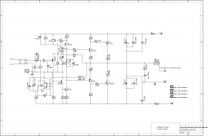
I think the output is wrong with R26...it seemes to miss the 10R//6uH before the 0.22R (R26)!
The original Mooly schematic!
Prasi,
Sorry, I guess I did not understand what information was conveyed in our PM's. If the Moderators agree post #702 can be removed, and a GB will not be persued.
Prasi, I will PM you when I decide on my individual requirements, all of course with permission of Mooly.
Best Regards,
Myles
I have no problem if any of you want to produce PCB's and sell them as a group buy
What is the purpose of R26? It seems to be redundant.
Regards ...
R26 slightly raises the output impedance changing the way the amplifier interacts with a varying speaker impedance. It is a fundamental part of the design as a whole.
I would advise anyone not to start changing and altering things until you have become fully familiar with how the original design performs when built as intended.
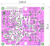
A good friend asked if its possible to make it as a single pair output and reduce the length to less than 100mm to take advantage of low board costs from China .
.
I gave it a try and here is the result.
It has the same features of the earlier board (caps, resistors, etc, even the logo).
regards
Prasi
.I gave it a try and here is the result.
It has the same features of the earlier board (caps, resistors, etc, even the logo
).regards
Prasi
Attachments
Last edited:
R26 Q&A
Fair enough. I just wanted to check if R26 was a relic or intentional. The main reason I was running a simulation was to check how sensitive the bias current will be for varying R8. And, it was an excuse to see if the TI psice model for the TL071D would work at all.
R26 slightly raises the output impedance changing the way the amplifier interacts with a varying speaker impedance. It is a fundamental part of the design as a whole.
Fair enough. I just wanted to check if R26 was a relic or intentional. The main reason I was running a simulation was to check how sensitive the bias current will be for varying R8. And, it was an excuse to see if the TI psice model for the TL071D would work at all.
- Home
- Amplifiers
- Solid State
- My MOSFET amplifier designed for music