Advice on removing AC Hum
I'm reaching out to the community because I can't seem to fix a ground loop hum on what I thought was only my left channel, but recently developed an intermittent hum on the right channel as well. I have been working on this off and on for 4 months trying to re-route wiring and other small changes to eliminate or at least reduce the AC hum.
I measure about 0.165mV of AC on the speaker out. I can get the right channel to behave adding a 10r resistor in line with the i/p GND and GND connection on the board. Takes it down to 0.20-0.30mVac.
However the left channel is being much more difficult. Even with the same ground scheme wire routing and adding the 10r resistor from i/p GND to GND, if you touch the top of C3 with my finger the AC hum comes back (without the 10r resistor is increases from 0.165mVac to 0.305mVac) The cap I'm using is a Kemet 470uF 25V polarized Aluminum Electrolytic.
I have tried three different PSU voltages (+/-30Vdc, +/-38Vdc and original +/-50Vdc), I have tried in and out of the chassis and just this weekend I tried adding 47p to each output mosfet from the G to S, as I saw in a couple other lateral mosfet schematics on DIYA. I have also removed all the small single transistors and replaced with Mouser/Digikey confirmed ones, in case they were fakes (left right with old ones, to compare) but no change to the hum.
I would appreciate any suggestions I could try, as throughout this thread there are others building this amp and not having any issues with hum. It does play music, does not overheat and sounds good when I play the right channel and there is no AC hum.
First thing is to try and quantify the 'hum'. Is it a pure and deep tone or more of a buzz (a bit raspy). So that would be a 60Hz sine for a pure deep tone and 120Hz ripple type waveform for a raspy buzz.
Pure and deep suggests a true ground loop, raspy would be more of a wiring issue in the way it all connects up.
Intermittent is odd, that perhaps suggests mains 'quality' is a factor and that might point to more of a wiring issue than a true ground loop.
Basic steps would be to power one channel with the input shorted at the board. Nothing else connected to it apart from the supplies. It should be silent.
Now do the same for the second channel. That should be silent as well.
If the two input grounds are now temporarily joined (as will happen anyway when you couple it up to something) then both channels should still be silent.
Have a read from post #14 here:
3 stage LIN topology - NFB tappings?
Intermittent is odd, that perhaps suggests mains 'quality' is a factor and that might point to more of a wiring issue than a true ground loop.
Regarding a potential mains quality issue, you could try using a different circuit in the house to determine if the specific branch from the mains load center has issues.
I should say intermittent may not be the best descriptor - what I mean is it works, but if you touch C3 it injects the Hum into the otherwise working right channel, sometimes continuing until you turn the amp off and back on again. Where the left is constant hum and gets worse touching C3.
I have been hesitant to measure with my scope, as I didn't want to blow up my scope with my ignorance. I will try and get a scope picture posted in the next couple of days.
Thanks for the link Mooly - I read that a couple years back, and went back through it now and I'll read it again slowly over the next few days.
I have tried a number of wiring schemes and all of them using tightly twisted power, speaker and Mogami shielded input wires. What's so confusing is this is first time I have had an hum issue I couldn't resolve with wire management, input shielding or 10r resistor breaking the ground.
But that's DIY, which for me likely means a very small oversight I haven't realized yet or one wiring scheme I haven't tried. Will keep trying, because I really like the amp and hate to give up on anything.
Last edited:
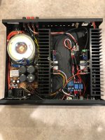
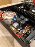
picture of the amp and psu
Couple pics below Vunce and thanks for looking.
It is a recycled Chassis & PSU, 36VAC toroidal to 4x80V 8200uF caps then going to the amp boards. The relay is out of the picture, it has a jumper to always turn on the PSU when the front switch is pushed.
I have a 5-second delay speaker protection as well, powered by +15V from the 7815 regulator on the PSU board, also used for the front panel LED. Have disconnected both speaker protection and LED and still get the same hum.
I have +/0/- from the PSU to each amp board (tightly twisted together), the "0" from the PSU goes to the GND of the speaker protection and to the negative speaker posts. Speaker positive output is straight off the board, with a 6uH inductor inline.
I will reiterate, that the hum is the same in the chassis and out of the chassis and when it is out of the chassis I use my test bench setup (28VAC toroidal with 4x1000uF caps) with alligator clips which I have used to test 5 other DIY amps and I get no hum, or very little that goes away with moving the wiring around.
This all points me to a problem/part on the board, but I have gone through both channels multiple times and find no incorrect parts of any out of spec. Also have checked all the soldering as well, even cleaned it again with alcohol to make sure flux was causing the issue.
Attachments
Last edited:
I'm having trouble wrapping my brain around having the black binding posts connected directly to the power supply. Then the speaker protect board gets its power-ground directly from the supply board? Isn't that going to cause a ground offset at the amp-board-speaker-ground terminal?
Granted, it doesn't seem like the kind of issue that might cause your odd combination of symptoms -- 'touch C3 .. hum remains until power interrupted' -- and so forth. But might merit investigating.
When you say, 'disconnect the speaker protection', is that simply removing the power to it, or disconnecting all eight lines in and out for both channels?
Cheers
Last edited:
Couple pics below Vunce and thanks for looking.
This all points me to a problem/part on the board, but I have gone through both channels multiple times and find no incorrect parts of any out of spec. Also have checked all the soldering as well, even cleaned it again with alcohol to make sure flux was causing the issue.
Hi,
Please send us a better picture of your RCA connections. If the ground tabs of these two RCA are tied together this will create a ground loop. Try disconnecting the black wire I/P_Gnd on one of the 2 channels. If both channels produces music then the channel without the input gnd wire was already grounded from another path. If only 1 channel produce music then you will have to look elsewhere.
On your power supply pcb, you seem to have 4 black wires, is this your star ground?
Good luck
Eric
Last edited:
Maybe it's just me, but I don't like seeing the binding posts in the "power" section of your amp. You've made a clear division between the power section on the left of the pictures and the amplification section on the right. But then you kind of nullify that division by having the outputs way over to the left in the power section. Your problem sounds like a wiring problem, so keep the wiring as short and as organised as possible.
I would start with moving the outputs to the amplification section, therefore shortening the wires to eliminate any possibility of introducing hum on the wiring. That would also keep the ground wires of the amplification section in one part and the ground wires of the power supply in the other part of the amp. It may sound like nitpicking, but seperation is the first step to exclude both ground loops and hum pick-up.
I would start with moving the outputs to the amplification section, therefore shortening the wires to eliminate any possibility of introducing hum on the wiring. That would also keep the ground wires of the amplification section in one part and the ground wires of the power supply in the other part of the amp. It may sound like nitpicking, but seperation is the first step to exclude both ground loops and hum pick-up.
I should say intermittent may not be the best descriptor - what I mean is it works, but if you touch C3 it injects the Hum into the otherwise working right channel, sometimes continuing until you turn the amp off and back on again. Where the left is constant hum and gets worse touching C3.
I have been hesitant to measure with my scope, as I didn't want to blow up my scope with my ignorance. I will try and get a scope picture posted in the next couple of days.
Your scope should be safe. If you connect the ground clip of the probe to ground in the amplifier then the most voltage the scope can see is supply voltage.
If the scope is a USB type then check in the documentation as to what the maximum allowable DC input voltage is. Also check the maximum allowable AC voltage.
Measuring across the speaker terminals should pose no risk at all as the DC voltage should be close to zero.
I agree with Mooly and would add that you can make your scope "floating", ea not connected to your mains ground. When I was repairing CD-players we found out that with the tiny signal levels like for instance the direct output of the laserpower chip, a grounded scope would work, but significantly influence measurements. That influence disappeared when we disconneted our scopes from the mains earth.
@Rick PA Stadel - yes all grounds go back to the PSU board - amps, speaker protection negatives and LED. Correct, disconnected Protection, means I removed it completely and unhooked the LED and got the same Hum issue from amp boards.
@e_fortier - no the RCA input grounds are not connected together, each RCA has it's own Mogami shielded cable running directly to the input of the amplifier boards. used this shielded cable in many other amps without any hum issues. I have also disconnected the right channel and isolated the left - with the same Hum
@Tjrep - it is a recycled amplifier, so I didn't choose the binding post location. However, it has been used with a TDA7294 and LM3886 eBay amp boards without that causing any issues.
@Mooly - I tried the scope last night and I get some strange readings of 30MHz at 160mV and then touching C3 goes to 33MHz and 305mV. But I don't trust it yet, so I will try a different probe and see if I can get some pictures for you
@Tjrep - no way to isolate my scope at this time. I will try and find another amp board "out of storage" and then I can compare my scope findings to validate before I share any pictures.
ONE LAST THING - I have seen pictures of amps without the i/p connection wired. If I run my amp board that way, it starts to pull additional current and light the DBT. For obvious reasons, I have only done that for a few seconds to see if that changed my hum issues at all, it makes it much worse (I think it makes DC on the output). I have also run that i/p to the PSU ground, to the board ground and through a 10r resistor to board ground. All of these still produce a hum, but is significantly lower with the 10r resistor in line to board ground.
Thanks for all the suggestions, I will keep trying what you have proposed and let yo know if anything changes.
30Mhz at the amplitudes you are seeing is instability and oscillation. Touching C3 isn't really a valid state as it could well introduce noise and hash but untouched and there should be nothing at all.
I think we need to begin with basics and for you to couple up just one channel (either) and lets see if we can get that working correctly. That means just its power supply and speaker.
If the amp has been built to the diagram in post #1 then R1, the 22k is quite sufficient to terminate the amplifier input correctly. The amp should be silent in that state.
@prasi - good suggestion(s), but I have tried that, on both channels. Left is/has more hum and easy to make it hum. Right channel will hum, but is usually quiet with the 10r resistor in series with i/p gnd to Gnd on board.
@mooly - totally agree, which is why I took them out of the chassis and went back to y test bench, where historically I have never had significant Hum issues with previous amplifiers.
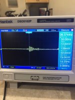
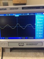
Here are scope pictures (remember I generally reset it to factory, then click on the "auto set" button to get my sine wave). I am very new to using a scope.
All pictures are with the left channel amplifier, input shorted and the output on a 8r dummy load.
#1 - is the scope noise floor, scope is connected but the amp is not powered on
#2 - amp is on, with i/p gnd routed to the GND terminal on the amp board
#3 - amp is on, with i/p gnd routed through a 10r resistor then to the GND terminal on the amp board.
@mooly - totally agree, which is why I took them out of the chassis and went back to y test bench, where historically I have never had significant Hum issues with previous amplifiers.
Here are scope pictures (remember I generally reset it to factory, then click on the "auto set" button to get my sine wave). I am very new to using a scope.
All pictures are with the left channel amplifier, input shorted and the output on a 8r dummy load.
#1 - is the scope noise floor, scope is connected but the amp is not powered on
#2 - amp is on, with i/p gnd routed to the GND terminal on the amp board
#3 - amp is on, with i/p gnd routed through a 10r resistor then to the GND terminal on the amp board.
Attachments
Lets try and get some baselines with these measurements.
1/ Do you get a flat trace with scope probe tip and ground lead shorted together but not connected to anything else? That has to be a yes really")
2/ With the amp OFF and its power supply unplugged from the mains do still get a flat trace if you connect the still shorted probe tip and ground lead to the negative speaker feed. That should be a yes as well.
3/ Now connect the scope to the speaker output as normal i.e ground and the amplifier output. You will have to take the feed from before the relay. Still a flat trace?
4/ Assuming it is you now connect the power supply to the mains but do not turn on the amp. In other words we now add the mains ground wire the the set up but with no power applied to the amp. Still flat?
(the 680k was something Aksa was experimenting with but it wasn't part of the original design).
Lets see where that gets us.
1/ Do you get a flat trace with scope probe tip and ground lead shorted together but not connected to anything else? That has to be a yes really
2/ With the amp OFF and its power supply unplugged from the mains do still get a flat trace if you connect the still shorted probe tip and ground lead to the negative speaker feed. That should be a yes as well.
3/ Now connect the scope to the speaker output as normal i.e ground and the amplifier output. You will have to take the feed from before the relay. Still a flat trace?
4/ Assuming it is you now connect the power supply to the mains but do not turn on the amp. In other words we now add the mains ground wire the the set up but with no power applied to the amp. Still flat?
(the 680k was something Aksa was experimenting with but it wasn't part of the original design).
Lets see where that gets us.
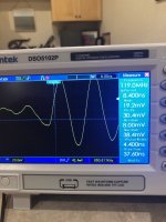
more scope findings
See my responses above in red - but everything you asked is flat on the scope. I am willing to resolder, remove, or change either the 22p C7 or 680k resistor if that might be something else to try.
Lets try and get some baselines with these measurements.
1/ Do you get a flat trace with scope probe tip and ground lead shorted together but not connected to anything else? That has to be a yes really
YES, it is flat and shows 0mV Avg. and 120mV Pk-Pk on scope at 1.0V/div
2/ With the amp OFF and its power supply unplugged from the mains do still get a flat trace if you connect the still shorted probe tip and ground lead to the negative speaker feed. That should be a yes as well.
Yes, it is flat, same as above
3/ Now connect the scope to the speaker output as normal i.e ground and the amplifier output. You will have to take the feed from before the relay. Still a flat trace?
Yes, it is flat, avg. still 0mV but Pk-Pk shows 200mV at 1.0V/div
4/ Assuming it is you now connect the power supply to the mains but do not turn on the amp. In other words we now add the mains ground wire the the set up but with no power applied to the amp. Still flat? Yes, it is flat with same 0mV avg. and 200mV Pk-Pk at 1.0V/div.
(the 680k was something Aksa was experimenting with but it wasn't part of the original design).
Lets see where that gets us.
See my responses above in red - but everything you asked is flat on the scope. I am willing to resolder, remove, or change either the 22p C7 or 680k resistor if that might be something else to try.
- Home
- Amplifiers
- Solid State
- My MOSFET amplifier designed for music