Seems many cut their teeth on these modules in the 1980's as I did.
Built my 1st stereo amp with them along with RIAA preamp etc and it sounded great.
Then while 'testing' at my lodgings, the police turn up and said there had been a complaint. I told them ' why didn't next door just ask me to turn it down?' and they replied ' the complaint was from somebody in the next street' .... still makes me smile to this day")
PS the Celestions i was using at the time didn't last long - they shuffled off in a puff of smoke lol
Built my 1st stereo amp with them along with RIAA preamp etc and it sounded great.
Then while 'testing' at my lodgings, the police turn up and said there had been a complaint. I told them ' why didn't next door just ask me to turn it down?' and they replied ' the complaint was from somebody in the next street' .... still makes me smile to this day
PS the Celestions i was using at the time didn't last long - they shuffled off in a puff of smoke lol
Hello happy forum members ... I have a soft spot for this amp as this is how I started out in electronics going to my local Maplin store . then made this lovely mosfet amp and nearly shook my parents house to bits, just love the 80's when I started making these amps
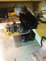
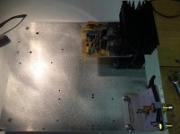
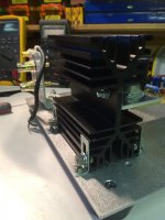
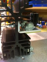
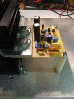
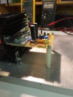
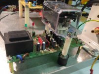
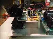
so now that I have my new PCB have decided to make a test bench to make sure all is ok with the amp before I commit to a pair of expensive cases etc
so now that I have my new PCB have decided to make a test bench to make sure all is ok with the amp before I commit to a pair of expensive cases etc
Last edited:


Here is my set of Maplin amps.
Maplin mosfet amp.
Maplin 50 watt hifi amp
Maplin 225wrms disco amplifier.
Hello Nigel ... happy days indeed
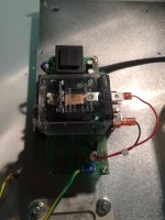
few more pics .. I have used a Velleman speaker protection module but have made a few mods
Like one heavy duty relay, and modded to PCB so both input channels can be used for a mono amplifier (dual redundancy)
plus played around with the timing capacitor for power up start up etc
Like one heavy duty relay, and modded to PCB so both input channels can be used for a mono amplifier (dual redundancy)
plus played around with the timing capacitor for power up start up etc
Attachments
The 100W Maplin amp was a great implementation of the original Hitachi design and I've put together loads of them. The same circuit works well with HEXFETs too with minimal circuit changes. I cant tell the difference between this design and more advanced efforts.
A great trip down memory lane really!
A great trip down memory lane really!
I built two Maplin mosfet amplifiers back in 1993. I noticed a difference in the circuit regarding the 10 ohm resistor in parallel with the output inductor. The instruction leaflet stated that the resistor is not provided or required.
Older Maplin mosfet kits included the resistor and stated that it was for damping the inductor to prevent ringing.
Has anybody on here done a square wave test on the amplifier to determine if the resistor is required or not.
Older Maplin mosfet kits included the resistor and stated that it was for damping the inductor to prevent ringing.
Has anybody on here done a square wave test on the amplifier to determine if the resistor is required or not.
Hi Guys,
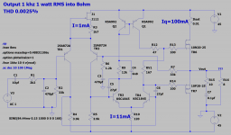
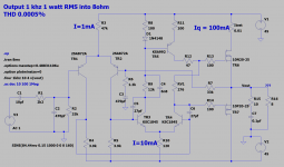
Before starting a build of the famous Maplin 100W Mosfet amp, I have been experimenting with LTspice (original file by Mooly?).
I have 2SA872A trannies for the LTP and Exicon 10P20/10N20 latfets for the outputs.
I cannot find the original 2SB716/2SD756 but have plenty of KSC992/1845 instead which look pretty similar (120V, high hFE, low Cob).
Some have used MPSA42/92 but the ones in my stash have pretty low hFE <100.
The simulation is very promising with a 0.0005% THD @1W.
I have tried next to add a J112 CCS and a current mirror, keeping the LTP/VAS/output current values nominal.
In these conditions the predicted THD is 0.0025%.
Is it expected to have a higher THD with CCS and CM? Do I miss something?
Jacques
Attachments
No degeneration resistors in the current mirror.
I only see a very marginal improvement.
No degeneration resistors in the current mirror.
Yes needs 100r in each leg.
I just used off the shelf cheapo transistors on my updated version.
MPSA92 and MPSA42 high voltage general purpose transistors.
Hello
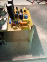
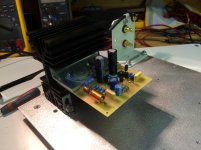
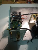
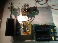
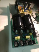
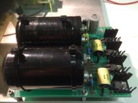
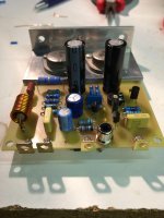
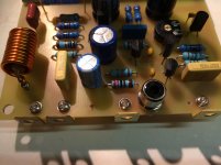
A couple of pics of the final PCB completed .. I have used 90 degree angle pcb tags for all connections and a phono connector for the input.
I know lots of people complain about hum with this PCB design but in my configuration I have always had very good results ??
A couple of pics of the final PCB completed .. I have used 90 degree angle pcb tags for all connections and a phono connector for the input.
I know lots of people complain about hum with this PCB design but in my configuration I have always had very good results ??
Attachments
A couple of pics of the final PCB completed ..
Hi James,
I like the RCA connector, how deep does it extend under the board?
Where do you source it?
Cheers,
Jacques
- Home
- Amplifiers
- Solid State
- Maplin MosFET Amplifier Ga28f construction thread