Big-Horn Notes (2)
The horn you have in mind is the wrong one. It is Freehafer's horn popularized by Geddes.
What is being addressed here is Salmon's horn family of which just one member is Exponential, [T] = 1
See attached Plach article for details.
At the wave lengths you are working with, length adjustments to the horn available to you are at best, trivial.
Because the horn size is so large, horn parameters are less critical; thus, modeling software should get you close enough. Back chamber volume adjustment and drive signal equalization are all that should be needed to tweak driver/horn performance.
Regards,
WHG
A hyperbolic horn is less adjustable on the driver end.
The horn you have in mind is the wrong one. It is Freehafer's horn popularized by Geddes.
What is being addressed here is Salmon's horn family of which just one member is Exponential, [T] = 1
See attached Plach article for details.
The advantage of a true exponential horn is that I may lengthen or shorten the back end of the horn, to achieve various throat cross-sectional areas, and various driver configurations - to see what sounds best.
At the wave lengths you are working with, length adjustments to the horn available to you are at best, trivial.
I'll have to give this more thought. My biggest hesitation with this project, is that any mistakes are set in stone. . . .
Because the horn size is so large, horn parameters are less critical; thus, modeling software should get you close enough. Back chamber volume adjustment and drive signal equalization are all that should be needed to tweak driver/horn performance.
Regards,
WHG
Attachments
Last edited:
The horn you have in mind is the wrong one. It is Freehafer's horn popularized by Geddes.
What is being addressed here is Salmon's horn family of which just one member is Exponential, [T] = 1
What exactly is the wrong horn I have in mind? A pure exponential (T = 1)? You recommended a hyperbolic-cosine horn of T = 0.6, is this the right horn? Below is my reasoning for wanting to build a pure exponential horn (via example):
A 15 Hz exponential horn (T = 1) requires a 41.6 m^2 mouth (assume full-space for sake of example). With a 6” throat (about 0.018 m^2), the horn is 14.09 meters long. And with a 15” throat (about 0.12 m^2), the horn is 10.64 meters long. That’s a difference of over 11 feet in horn length between the two throat sizes - which is far from trivial. Assume for the moment that I cast my horn to run a single driver with a 6” throat, no problem. But if I want to try running several drivers feeding a common 15” throat? I’ll need to literally cut 11 feet off the back of my horn to achieve the cross-sectional area. This is why I desire to build my horn with the 15” throat initially (hypothetically – I haven’t finalized an actual throat size) – this way I may fabricate the back-end of the horn out of wood - with various lengths, for various throat sizes, and for various driver configurations – all using the common cast concrete horn. This is possible because horn geometry is constant (pure exponential expansion of cross-sectional area) when T = 1.
Now assume T = 0.6, same 15 Hz cutoff frequency, same 41.6 m^2 mouth: With a 6” throat the horn is 14.91 meters long. And with a 15” throat the horn is 11.49 meters long. Again, a difference of over 11 feet in horn length. But this time I cannot cast the horn with a 15” throat, and simply extend it back for a smaller throat – because the rate of exponential expansion is not constant down the horn's axis when T = 0.6, because the overall horn shape is a function of the throat cross-sectional area.
I acknowledge that a hyperbolic-cosine horn has better loading down to the cutoff frequency, but it also means I must select a final throat area in the design phase now, which then becomes fixed forever when the horn is cast in concrete. Do I need a single 12" or 15" driver loading a small throat? Or do I need multiple drivers feeding a small chamber, into a larger throat? I don't know. And to the best of my knowledge, no one has ever built a full size 15 Hz horn from concrete, for me to ask.
Design is all about addressing the initial unknowns
The hyperbolic horn that would present neck adjustment problems is that developed by Freehafer/Geddes. Here curvature in the neck region is pronounced. In the case of Salmon's family, where 1 >= [T] >= 0, curvature is at a minimum and any variant in this domain can be accommodated. Note here that in all cases, we are dealing with essentially straight throat walls, except in the round to rectangular transition if one is used to join horn to driver(s). If you change driver configuration, this is where you would implement the change. As Klipsch demonstrated with his "Rubber Throat", the flare rate here may be different than that of the connected horn.
What exactly is the wrong horn I have in mind?
The hyperbolic horn that would present neck adjustment problems is that developed by Freehafer/Geddes. Here curvature in the neck region is pronounced. In the case of Salmon's family, where 1 >= [T] >= 0, curvature is at a minimum and any variant in this domain can be accommodated. Note here that in all cases, we are dealing with essentially straight throat walls, except in the round to rectangular transition if one is used to join horn to driver(s). If you change driver configuration, this is where you would implement the change. As Klipsch demonstrated with his "Rubber Throat", the flare rate here may be different than that of the connected horn.
A pure exponential (T = 1)?
That is one choice, but not necessarily acoustically superior to others.
You recommended a hyperbolic-cosine horn of T = 0.6, is this the right horn?
No! I recommended you start model exploration at that setting.
Below is my reasoning for wanting to build a pure exponential horn (via example):
The throat sizes anticipated by these hypotheticals are way too small, and of course lead to large length variations which are unnecessary.
A 15 Hz exponential horn (T = 1) requires a 41.6 m^2 mouth (assume full-space for sake of example). With a 6” throat (about 0.018 m^2), the horn is 14.09 meters long. And with a 15” throat (about 0.12 m^2), the horn is 10.64 meters long. That’s a difference of over 11 feet in horn length between the two throat sizes - which is far from trivial. Assume for the moment that I cast my horn to run a single driver with a 6” throat, no problem. But if I want to try running several drivers feeding a common 15” throat? I’ll need to literally cut 11 feet off the back of my horn to achieve the cross-sectional area. This is why I desire to build my horn with the 15” throat initially (hypothetically – I haven’t finalized an actual throat size) – this way I may fabricate the back-end of the horn out of wood - with various lengths, for various throat sizes, and for various driver configurations – all using the common cast concrete horn. This is possible because horn geometry is constant (pure exponential expansion of cross-sectional area) when T = 1.
Now assume T = 0.6, same 15 Hz cutoff frequency, same 41.6 m^2 mouth: With a 6” throat the horn is 14.91 meters long. And with a 15” throat the horn is 11.49 meters long. Again, a difference of over 11 feet in horn length. But this time I cannot cast the horn with a 15” throat, and simply extend it back for a smaller throat – because the rate of exponential expansion is not constant down the horn's axis when T = 0.6, because the overall horn shape is a function of the throat cross-sectional area.
I acknowledge that a hyperbolic-cosine horn has better loading down to the cutoff frequency, but it also means I must select a final throat area in the design phase now, which then becomes fixed forever when the horn is cast in concrete.
That is a requirement that should be met independent of the [T] setting used, long before you start pouring concrete.
Do I need a single 12" or 15" driver loading a small throat? Or do I need multiple drivers feeding a small chamber, into a larger throat? I don't know. And to the best of my knowledge, no one has ever built a full size 15 Hz horn from concrete, for me to ask.
When you have completed large signal analysis and determined driver [VD] requirements, then [St] can be set that balances efficiency against distortion and driver Xmax. These are not mystical unknowns that need be postponed and addressed in a post construction phase. Note use of an [St]/[Sd] < 1 ratio is contra indicated here due to outdoor venue. Such arrangements present opportunity for moisture and debris entrapment that should be avoided. Given this venue, use of drivers with polypropylene (or equivalent waterproof) diaphragms is recommended.
WHG
Last edited:
Majectic Beast
The only horns that come close are the Royal Device and MOAS.
WHG
And what I mean by full-size, is in fact a 15 Hz half-space horn (loading the ground plane).
The only horns that come close are the Royal Device and MOAS.
WHG
Attachments
In the case of Salmon's family, where 1 >= [T] >= 0, curvature is at a minimum and any variant in this domain can be accommodated. Note here that in all cases, we are dealing with essentially straight throat walls...WHG
The cross-sectional area near the throat changes disproportionately slowly in a hyperbolic-cosine horn (T < 1) - aka "essentially straight throat walls". This means length adjustments cannot be accomplished on the back-side of the horn after it is cast - for the purpose of adjusting throat area - should I construct a hyperbolic-cosine horn, whereas I could adjust the horn if I build it exponential (T = 1). Note that I have never contemplated building an exponential-sine horn (T > 1).
A single 15" long-throw driver, loaded into a 6" or 8" throat of a 15 Hz exponential-cosine horn should sound pretty amazing. Do I need multiple drivers feeding a larger throat? I'm not sure. The advantage of a gigantic horn is ideal impedance matching at the driver. The larger the throat, the larger the impedance mismatch. This is a backyard system within a neighborhood of 5-acre lots, with the intended purpose of throwing an occasional outdoor party in the summertime. Yes it needs to play loud enough, but I'm willing to sacrifice ultimate SPL for increased fidelity. The whole goal of this project is being able to achieve both. I don't require that the horn be able to play uncomfortably loud.
That being said - if you have a T value in mind, and driver configuration (size & quantity) for the throat, as well as throat cross-sectional area - I welcome your input. Previous recommendations were to build a short horn, with a gigantic throat, and load it with (qty 20) 18" drivers. This sorta defeats the purpose of building a horn - IMHO.
Mega-Horn Notes (3)
At a [Fc] = 15 Hz, horn wall slope differences for various 1>=[T]>0.5 settings are miniscule.
Consideration needs to be given to the transition needed to connect driver(s) selected to the horn throat.
Issues to be addressed include:
1) Changing the fixed slope of the roof wall to avoid negative side-wall slopes
2) Front cavity design (no phase plug needed)
3) Round to rectangular throat section transition(s)
While doing all of this, even a zero area expansion rate can be used without deleterious effect on system performance.
Better “fidelity” will be achieved with a smaller [Xmax] and larger [Sd] for the same [VD], whatever it may be.
If the horn throat is too small, distortion will be higher than whatever is acceptable.
You need to determine system large signal requirements that will deliver the desired SPL at the listening area, at the lowest frequency of interest.
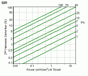
See attached chart to address the throat distortion issue.
Note that where this issue is critical is at the upper end of sub-woofer system bandwidth.
The other issue is air-flow turbulence at the lower end.
Somewhere between the extremes addressed here is where you need to be.
This is your project, and you get to do the "grunt work". I do not do acoustic design pro bono, because my spare time is limited to providing constructive advice here only.
WHG
The cross-sectional area near the throat changes disproportionately slowly in a hyperbolic-cosine horn (T < 1) - aka "essentially straight throat walls". This means length adjustments cannot be accomplished on the back-side of the horn after it is cast - for the purpose of adjusting throat area - should I construct a hyperbolic-cosine horn, whereas I could adjust the horn if I build it exponential (T = 1). Note that I have never contemplated building an exponential-sine horn (T > 1).
At a [Fc] = 15 Hz, horn wall slope differences for various 1>=[T]>0.5 settings are miniscule.
Consideration needs to be given to the transition needed to connect driver(s) selected to the horn throat.
Issues to be addressed include:
1) Changing the fixed slope of the roof wall to avoid negative side-wall slopes
2) Front cavity design (no phase plug needed)
3) Round to rectangular throat section transition(s)
While doing all of this, even a zero area expansion rate can be used without deleterious effect on system performance.
A single 15" long-throw driver, loaded into a 6" or 8" throat of a 15 Hz exponential-cosine horn should sound pretty amazing. Do I need multiple drivers feeding a larger throat? I'm not sure. The advantage of a gigantic horn is ideal impedance matching at the driver. The larger the throat, the larger the impedance mismatch. This is a backyard system within a neighborhood of 5-acre lots, with the intended purpose of throwing an occasional outdoor party in the summertime. Yes it needs to play loud enough, but I'm willing to sacrifice ultimate SPL for increased fidelity. The whole goal of this project is being able to achieve both. I don't require that the horn be able to play uncomfortably loud.
Better “fidelity” will be achieved with a smaller [Xmax] and larger [Sd] for the same [VD], whatever it may be.
If the horn throat is too small, distortion will be higher than whatever is acceptable.
You need to determine system large signal requirements that will deliver the desired SPL at the listening area, at the lowest frequency of interest.
See attached chart to address the throat distortion issue.
Note that where this issue is critical is at the upper end of sub-woofer system bandwidth.
The other issue is air-flow turbulence at the lower end.
That being said - if you have a T value in mind, and driver configuration (size & quantity) for the throat, as well as throat cross-sectional area - I welcome your input. Previous recommendations were to build a short horn, with a gigantic throat, and load it with (qty 20) 18" drivers. This sorta defeats the purpose of building a horn - IMHO.
Somewhere between the extremes addressed here is where you need to be.
This is your project, and you get to do the "grunt work". I do not do acoustic design pro bono, because my spare time is limited to providing constructive advice here only.
WHG
Attachments
Last edited:
Whgiger, the Plach paper you posted (thank you for posting it by the way), has an equation on page 5 for horn distortion – where a 15 Hz horn, playing 150 Hz, with a 6” throat, can reproduce 127.23 acoustical Watts (141 dB) at just under 1% distortion. The graph you’ve linked above however indicates 1% distortion will occur at 9 acoustical Watts (or 129 dB). That’s a very appreciable difference. What is the source of your graph?
Assume a typical compression horn (1 kHz cutoff), playing at 10 kHz, with a standard 1.4” throat. Using the graph, 1% distortion happens at 0.5 acoustical Watts (117 dB). Using the Plach equation however, 1% distortion occurs at 6.9 acoustical Watts (128 dB). Both references cannot be correct.
Nonetheless, the entire geometry of a non-exponential (aka hyperbolic-cosine horn) is a function of the throat area. A 15 Hz (T = 0.6) horn with a 6” diameter throat will have a substantially different overall length, with very appreciable differences in overall curvature down the axis - compared to a 15” throat horn.
Only a true exponential horn can be lengthened (or shortened) on the throat end, to achieve various throat areas – without changing the overall horn geometry. That being said – I like the impedance loading-curve of the hyperbolic-cosine (T = 0.6) horn. To build a T = 0.6 horn, I must select a throat area now (without experimentation), then cast the entire horn geometry based on that value (i.e. zero adjustments on throat area after the horn is cast).
Assume a typical compression horn (1 kHz cutoff), playing at 10 kHz, with a standard 1.4” throat. Using the graph, 1% distortion happens at 0.5 acoustical Watts (117 dB). Using the Plach equation however, 1% distortion occurs at 6.9 acoustical Watts (128 dB). Both references cannot be correct.
At a [Fc] = 15 Hz, horn wall slope differences for various 1>=[T]>0.5 settings are miniscule.
Nonetheless, the entire geometry of a non-exponential (aka hyperbolic-cosine horn) is a function of the throat area. A 15 Hz (T = 0.6) horn with a 6” diameter throat will have a substantially different overall length, with very appreciable differences in overall curvature down the axis - compared to a 15” throat horn.
Only a true exponential horn can be lengthened (or shortened) on the throat end, to achieve various throat areas – without changing the overall horn geometry. That being said – I like the impedance loading-curve of the hyperbolic-cosine (T = 0.6) horn. To build a T = 0.6 horn, I must select a throat area now (without experimentation), then cast the entire horn geometry based on that value (i.e. zero adjustments on throat area after the horn is cast).
What is the source of your graph?
It would appear to be based on the equation and associated chart for the second-harmonic distortion of an infinite exponential horn, as given in Beranek's "Acoustics" textbook.
Assume a typical compression horn (1 kHz cutoff), playing at 10 kHz, with a standard 1.4” throat. Using the graph, 1% distortion happens at 0.5 acoustical Watts (117 dB).
I am not sure that you are interpreting the chart correctly
") .
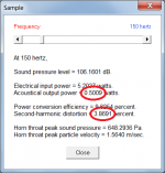
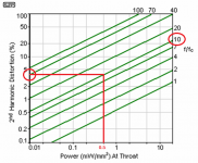
.Power output = 0.5 acoustical watts
Throat diameter = 1.4 inches
Throat area = Pi * (1.4 * 2.54 / 2) ^ 2 = 9.93 cm2
Power density at throat = 0.5 / 9.93 = 0.05 W/cm2 = 0.5 mW/mm2
For 0.5 mW/mm2 and f/fc = 10 the second-harmonic distortion is close to 4 percent.
The result is consistent with that generated by Hornresp at 150 Hz for an infinite exponential horn having S1 = 9.93 cm2 and F12 = 15 Hz.
Attachments
Power density at throat = 0.5 / 9.93 = 0.05 W/cm2 = 0.5 mW/mm2
"Power density at throat" should read "Sound intensity at throat".
I am not sure that you are interpreting the chart correctly
I made a type-o last night on the calculator - meant to say 0.05 Watts gives 1% (which is 107 dB). Again, the Plach equation states 1% "second harmonic distortion" happens at 6.9 acoustical Watts (128 dB). This is a fantastic disparity. My assumption is that the Plach paper is simply in-error.
I'm trying to determine the maximum acceptable air-velocity in the throat for a bass horn. All I've been able to find are discussions towards the non-linearity of air compression, and how it relates to generating second harmonic distortion (i.e. power density limits). Are there other rule-of-thumbs for minimizing throat noise? Such as simply rounding the edges of the throat entry - to minimize turbulence. At which point does air-velocity in a horn throat become troublesome?
I need multiple drivers to get adequate sound pressure near my cutoff frequency. I'm thinking a simple square box, with (qty 1) driver mounted on 5 of the 6 box sides, where the 6th side is bolted to the horn's throat. Obviously there'd be an outer box also. Is there any benefit to keeping the rear of each driver within separate chambers, or is a common box ok? My assumption is that I need to minimize the volume of the front chamber, and keep the throat as small as possible also - without going too small.
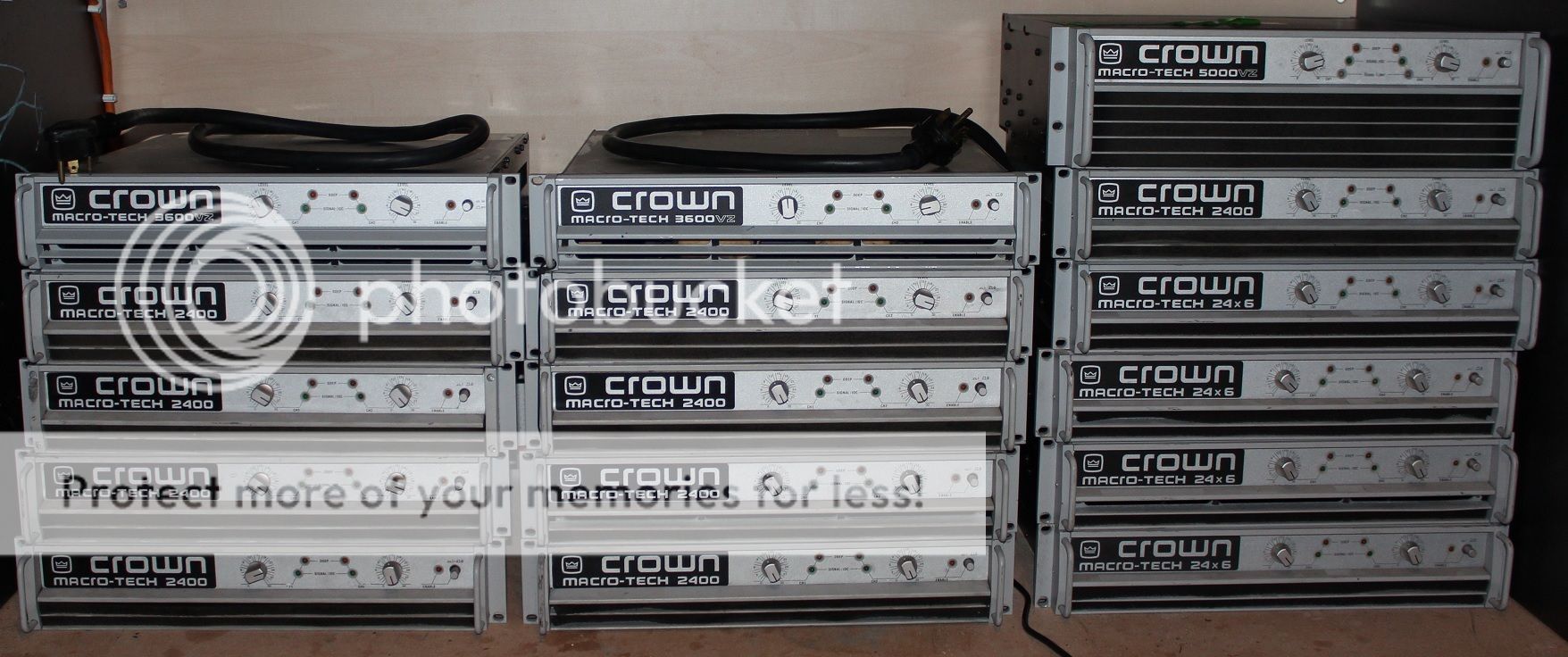
Here are some of the amplifiers I've picked up for this project. I need to replace a few missing handles, and two of the MA-3600VZ are missing their air filter elements. The insides are clean, thus I don't think they were actually run without filters. Also available for this project (but not pictured) are (qty 2) DC-300A, (qty 1) MA-3600VZ, (qty 1) MA-5002VZ, and (qty 1) MT-1200.
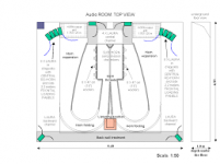
I need to build a climate-controlled structure to house the electronics. The logical place is on the backside of the horn - probably 15 x 25 foot, wired for 200 amperes (240/120 volt single-phase). Obviously with a good dehumidifier.
Last edited:
Horn Distortion Issue
I will provide information to help you with these issues.
Note that Plach is using Imperial UOMs.
The graph provided earlier is probably from Beranek (LLB).
See attachments that address horn distortion.
Regards,
WHG
I made a type-o last night on the calculator - meant to say 0.05 Watts gives 1% (which is 107 dB). Again, the Plach equation states 1% "second harmonic distortion" happens at 6.9 acoustical Watts (128 dB). This is a fantastic disparity. My assumption is that the Plach paper is simply in-error.
I'm trying to determine the maximum acceptable air-velocity in the throat for a bass horn. All I've been able to find are discussions towards the non-linearity of air compression, and how it relates to generating second harmonic distortion (i.e. power density limits). Are there other rule-of-thumbs for minimizing throat noise? Such as simply rounding the edges of the throat entry - to minimize turbulence. At which point does air-velocity in a horn throat become troublesome?
I need multiple drivers to get adequate sound pressure near my cutoff frequency. I'm thinking a simple square box, with (qty 1) driver mounted on 5 of the 6 box sides, where the 6th side is bolted to the horn's throat. Obviously there'd be an outer box also. Is there any benefit to keeping the rear of each driver within separate chambers, or is a common box ok? My assumption is that I need to minimize the volume of the front chamber, and keep the throat as small as possible also - without going too small.
I will provide information to help you with these issues.
Note that Plach is using Imperial UOMs.
The graph provided earlier is probably from Beranek (LLB).
See attachments that address horn distortion.
Regards,
WHG
Attachments
Last edited:
Air-Flow Turbulance at Horn Throat Entry
While I am unaware of any studies that address the subject issue, the attached article does address the relevant physics of the matter.
This I suspect none have be published for horns due to limited commercial interest in building horns to reproduce the last octave of the musical spectrum.
WHG
While I am unaware of any studies that address the subject issue, the attached article does address the relevant physics of the matter.
This I suspect none have be published for horns due to limited commercial interest in building horns to reproduce the last octave of the musical spectrum.
WHG
Attachments
Standing Waves
Only when dimensions (diagonals included) exceed say 1 meter, should standing wave problems arise. WHG
I need multiple drivers to get adequate sound pressure near my cutoff frequency. I'm thinking a simple square box, with (qty 1) driver mounted on 5 of the 6 box sides, where the 6th side is bolted to the horn's throat. Obviously there'd be an outer box also. Is there any benefit to keeping the rear of each driver within separate chambers, or is a common box ok? My assumption is that I need to minimize the volume of the front chamber, and keep the throat as small as possible also - without going too small.
Only when dimensions (diagonals included) exceed say 1 meter, should standing wave problems arise. WHG
Thank you for the links. I'm slowly working my way through them. Equation 9.33 within the LLB3.PDF file seems to correlate with both the Hornresp program, and the graph you posted on #1187. It also seems that for smaller values of T (i.e. hyperbolic-cosine horns) that the distortion problem is more pronounced - doesn't say by how much. The majority of the equations were derived using pure exponential (and/or conical) expansion. I found a journal article (I'm not sure if I'm permitted to repost the graph) which shows that second harmonic distortion less than 2.5% is not audible to the ear, from frequencies 100 Hz and lower - provided the listening level is 110 dB or more (the threshold is actually 5% at 20 Hz). When the listening volume is decreased however, the threshold for hearing harmonic distortion decreases appreciably - to 1.4% at 80 dB at 50 Hz. Very interesting. It would appear the 1% rule is more applicable to midrange horns, and that bass horns can have upwards of 3% harmonic distortion with satisfactory fidelity.
Per the AESP4661A.PDF file, shear-vortices cause noise. Prominent disruption of the boundary layer occurs at 25 m/s. The larger the radius of the port entry, the less likely you'll shear & generate a vortex. Is this a valid rule for a horn throat also? It seems reasonable? However 25 m/s is very fast.
I was tinkering in Hornresp - a 15 Hz half-space horn (T = 0.47), with (qty 5) 18" B&C drivers (14-mm Xmas) feeding a 20" diameter throat, will crank out 141 dB from 15 Hz to 150 Hz, without exceeding driver Xmax. Throat velocity at this SPL is 6 m/s (near fc), but second harmonic distortion at 150 Hz is 11.3%. Considering sound levels for public venues are typically limited to 105 dB, and 123 dB for 25-80 Hz bass frequencies, I'd say 141 dB is completely overkill for my backyard. The 11.3% distortion is a bit of a turnoff also. BUT - if I simply turn down the volume to 125 dB, second harmonic distortion at 150 Hz drops to 1.6%. That would be completely amazing - a bass horn that can play 15 Hz to 150 Hz at 125 dB, with less than 2% distortion! It would appear that harmonic distortion is the dominant variable, and not throat velocity. I'll still make sure there are no sharp leading-edges in the throat nonetheless. Note: I initially had no intention of using five 18" drivers, however my 15 Hz cutoff frequency requires an appreciable amount of cone displacement. . . . I'm still undecided. Design recommendations are welcome!
Big-Horn Notes (4)
Some headroom is a good thing to pass transients unscathed.
I see no problem reposting the graph.
Just in case of moderator redaction, copy the attached files to your system, as 'fair use' is not iron clad here and elsewhere. WHG
Thank you for the links. I'm slowly working my way through them. Equation 9.33 within the LLB3.PDF file seems to correlate with both the Hornresp program, and the graph you posted on #1187. It also seems that for smaller values of T (i.e. hyperbolic-cosine horns) that the distortion problem is more pronounced - doesn't say by how much. The majority of the equations were derived using pure exponential (and/or conical) expansion. I found a journal article (I'm not sure if I'm permitted to repost the graph) which shows that second harmonic distortion less than 2.5% is not audible to the ear, from frequencies 100 Hz and lower - provided the listening level is 110 dB or more (the threshold is actually 5% at 20 Hz). When the listening volume is decreased however, the threshold for hearing harmonic distortion decreases appreciably - to 1.4% at 80 dB at 50 Hz. Very interesting. It would appear the 1% rule is more applicable to midrange horns, and that bass horns can have upwards of 3% harmonic distortion with satisfactory fidelity.
Per the AESP4661A.PDF file, shear-vortices cause noise. Prominent disruption of the boundary layer occurs at 25 m/s. The larger the radius of the port entry, the less likely you'll shear & generate a vortex. Is this a valid rule for a horn throat also? It seems reasonable? However 25 m/s is very fast.
I was tinkering in Hornresp - a 15 Hz half-space horn (T = 0.47), with (qty 5) 18" B&C drivers (14-mm Xmas) feeding a 20" diameter throat, will crank out 141 dB from 15 Hz to 150 Hz, without exceeding driver Xmax. Throat velocity at this SPL is 6 m/s (near fc), but second harmonic distortion at 150 Hz is 11.3%. Considering sound levels for public venues are typically limited to 105 dB, and 123 dB for 25-80 Hz bass frequencies, I'd say 141 dB is completely overkill for my backyard. The 11.3% distortion is a bit of a turnoff also. BUT - if I simply turn down the volume to 125 dB, second harmonic distortion at 150 Hz drops to 1.6%. That would be completely amazing - a bass horn that can play 15 Hz to 150 Hz at 125 dB, with less than 2% distortion! It would appear that harmonic distortion is the dominant variable, and not throat velocity. I'll still make sure there are no sharp leading-edges in the throat nonetheless. Note: I initially had no intention of using five 18" drivers, however my 15 Hz cutoff frequency requires an appreciable amount of cone displacement. . . . I'm still undecided. Design recommendations are welcome!
Some headroom is a good thing to pass transients unscathed.
I see no problem reposting the graph.
Just in case of moderator redaction, copy the attached files to your system, as 'fair use' is not iron clad here and elsewhere. WHG
"Design recommendations are welcome!", you say? I have one.
I've read ALL 120 pages. Took a few days, but I did. I have zero engineering background but am fascinated by this DIYAUDIO website and read it for at least two hours a day. It is a rabbit hole that I love to run down. The world's problems fade as I immerse myself in reading about things like your project.
I deeply and truly admire your knowledge and ambition and willingness to chase "big, hairy, audacious goals".
But... If I recall correctly, you've never built a loudspeaker before. Two years of reading this site supports the conclusion that virtually nobody gets their first design completed to their own ultimate satisfaction.
List of people who died climbing Mount Everest - Wikipedia
And, I suspect that your level of being "ultimately satisfied" is orders of magnitude higher than that of most other people. Your project is fascinating on many levels.
Instead of fulfilling its intended purpose, a "less than satisfying to you" result risks...?
What if you stick to DIY'ing everything else about your home, yard and listening environment, but leave the speaker building to that guy named Danley that you've seen build a few big speakers that other people admire, sometimes 80,000 or so people at a time.
J5-4015 Caleb | Danley Sound Labs, Inc.
A pair of these would suffice? And, if they don't work out, there is a market for selling them. No harm, no foul.
I realize my design recommendation (design everything BUT the speakers) will not fall lightly upon your eyes and ears. But you DID asked for recommendations.
Bon Voyage!!!
PS If you don't post photos of your creation, and measurements, etc., it will like reading a copy of Moby Dick that has the last chapter ripped out.
Extrapolate Distortion Estimate for [T] < 1
Note that for an exponential horn
m = Ln(Sm/St)/l
& fc = m*c/(4*pi)
For the longer horn where [T] < 1
assume a longer [l] exponential horn and calculate a new [m] & [fc]
Now on this basis, reevaluate distortion levels from Beranek. WHG
Thank you for the links. I'm slowly working my way through them. Equation 9.33 within the LLB3.PDF file seems to correlate with both the Hornresp program, and the graph you posted on #1187. It also seems that for smaller values of T (i.e. hyperbolic-cosine horns) that the distortion problem is more pronounced - doesn't say by how much.
Note that for an exponential horn
m = Ln(Sm/St)/l
& fc = m*c/(4*pi)
For the longer horn where [T] < 1
assume a longer [l] exponential horn and calculate a new [m] & [fc]
Now on this basis, reevaluate distortion levels from Beranek. WHG
- Status
- This old topic is closed. If you want to reopen this topic, contact a moderator using the "Report Post" button.
- Home
- Loudspeakers
- Subwoofers
- Concrete Bass Horn Design Question