With no Rg, the very small output and input stage currents must flow in the same direction due to conservation of charge at their junction.
The DC input and offset current errors of any amplifier can go either way with output/input voltage or current due to layout issues, etc. You can also put large resistors from the output to the null pins to make Aol look positive, negative, or even infinite. This apparent positive feedback is only a curiosity. In other words you can make any IC op-amp with null pins look like Aol is negative and it does not matter to any closed loop application.
Last edited:
The DC input and offset current errors of any amplifier can go either way with output/input voltage or current due to layout issues, etc. You can also put large resistors from the output to the null pins to make Aol look positive, negative, or even infinite. This apparent positive feedback is only a curiosity. In other words you can make any IC op-amp with null pins look like Aol is negative and it does not matter to any closed loop application.
"Null pins"?
It's known as a voltage follower, what am I missing? There is no positive feedback.
Input and output stage currents both flow out of (or into) a substantial Rg in the same direction, in opposition, and we have negative feedback.
With no Rg, the very small output and input stage currents must flow in the same direction due to conservation of charge at their junction.
"Null pins"?
You never saw that? Walt Jung published it several times with respect to using an op-amp open-loop feeding back to the null pins. I was only referring to injecting an offset proportional to output, it makes the Aol have any sign you want (or null it to infinite). The point is you make a follower out of a CFA and you move the input stage up and down 10V you change all the Vce's around and change the small offset voltages and currents you need to equilibriate everything, this can be of either sign and does not matter to anything.
Last edited:
Could you please take the trouble to add these imperfections to the generally used transfer function of the CFA.
That will tell to what degree your comments are relevant and whether anybody is hitting his head.
No sims, just plain mathematics.
Hans
Post 1112 applies.
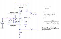
Please recall the hybrid pi model of a transistor with its vbe-controlled gm current source output in parallel with a resistor ro. It is derived for small signal operation directly from the Ebers-Moll model. ro and 1/gm combine to make up the Ro in the referenced post. I am not going to derive this; there are numerous sources on the web that you can find that will show you this if you are unfamiliar with it.
Now, you don't like sims. Will you next ask me to perform a bench test for you to demonstrate that there is a current that flows when Vce is held constant and vbe varies, and another one that flows when Vbe is held constant and vce varies?
I hope not.
If this fails to satisfy, please give us some idea of why the mathematics I have mentioned are inadequate to the task. I ask without a hint of sarcasm; I honestly don't know why they wouldn't be.
You never saw that? Walt Jung published it several times with respect to using an op-amp open-loop feeding back to the null pins. I was only referring to injecting an offset proportional to output, it makes the Aol have any sign you want (or null it to infinite).
Ahhh of course! I asked because honestly I didn't see the relevance of DC offset adjustment pins to our discussion.
And I hope you have considered after viewing post 1028 the possibility that the ro of the Early effect can be significant in determining AC collector current in the input transistor of a closed loop CFA.
And I hope you have considered after viewing post 1028 the possibility that the ro of the Early effect can be significant in determining AC collector current in the input transistor of a closed loop CFA.
No it doesn't, I've asked before simply measure the current into the - input and the displacement current in the compensation capacitor at say 1MHz. Your example has no compensation capacitor, most modern IC's are well beyond 3904's and 3906's and you would have to push into the models to find these currents.
No it doesn't, I've asked before simply measure the current into the - input and the displacement current in the compensation capacitor at say 1MHz. Your example has no compensation capacitor, most modern IC's are well beyond 3904's and 3906's and you would have to push into the models to find these currents.
Are there no discrete transistors then that can be substituted into the simulation that are "well beyond" the '3904's and '3906's in some manner? Surely there must be some. What are they?
The transistor models contain their own capacitances, do they not? Regardless, the open loop bandwidth of many CFAs extends beyond audio frequencies, in which case for the purposes of the simulation, the compensation capacitor's effects would be irrelevant.
The principle that high loop gain minimizes vbe but leaves vce unaffected is certainly valid.
I don't see the evidence for for dismissing post 1028's claim. Perhaps you can better point us towards it?
Why not name it after its most famous implementation?
We call the circuit in Figure 1 "the LH0002 buffer" after the NSC product.
You lost me the LH0002 is just a buffer there is no feedback and it is predated by decades in dozens of op-amps especially Harris.
CPaul I'm not sure what you are trying to proof and why. Is it the transfer function (I/V) of the Diamond or is it the current on demand of the IPS you are trying to show?
You can use ideal current mirrors and load the output of the mirrors with a R if it's the I/V you are looking for.
If it's the whole amp you are simulating with outputstage and feedback you must use a compensation cap as Scott is saying.
You can use ideal current mirrors and load the output of the mirrors with a R if it's the I/V you are looking for.
If it's the whole amp you are simulating with outputstage and feedback you must use a compensation cap as Scott is saying.
Did you get any patents? Do anything original? What was it?
THx-RNMarsh
I haven't seen any reason to patent the circuits most of it is known techniques put together to optimize the circuits, but it's a couple of things in one of the H-bridge amps that I haven’t seen before and might be worth a patent.
When it comes to my newest class D designing it is my own design from scratch and the performance is very promising. The THD is very low without higher order feedback loops and bad clipping behavior.
I was actually thinking of contacting someone that I trust and that knows how to take patents on circuits and having contacts in the manufacturing business. The core (comparator) of the amp can be used for a lot of applications other than Class D amps.
I see no reason in patenting a circuit without having the muscles and knowhow to protect the patent.
CPaul I'm not sure what you are trying to proof and why. Is it the transfer function (I/V) of the Diamond or is it the current on demand of the IPS you are trying to show?
You can use ideal current mirrors and load the output of the mirrors with a R if it's the I/V you are looking for.
If it's the whole amp you are simulating with outputstage and feedback you must use a compensation cap as Scott is saying.
What I'm doing and why should be clear from post 1028.
If I am only looking at 1kHz, and the CFA open loop bandwidth is above 1kHz, a compensation capacitor would have no effect at 1kHz, correct? So even if the transistors models included no capacitance, what effect would including one have on a 1kHz simulation?
1KHz might as well be DC, you are not exercising any important features of either circuit topology just looking at where the voltages and currents equilibrate.
What I'm doing and why should be clear from post 1028.
If I am only looking at 1kHz, and the CFA open loop bandwidth is above 1kHz, a compensation capacitor would have no effect at 1kHz, correct? So even if the transistors models included no capacitance, what effect would including one have on a 1kHz simulation?
No I don't think it's clear, that's why I asked.
And yes you are not correct, you have to use a Ccomp even if the transistor models include a C.
Maybe you could put words on what you are trying to show in that post?
Last edited:
1KHz might as well be DC, you are not exercising any important features of either circuit topology just looking at where the voltages and currents equilibrate.
Forgive me, but that seems very vague.
I assume adding it from the collector of Q5 to ground would be appropriate. What value would you like me to use?
If I add a compensation capacitor and get similar results in the simulation, will there be yet another barrier to accepting the post's conclusions?
I'm willing to be wrong and admit it. But you're going to have to help me demonstrate it if I am.
No I don't think it's clear, that's why I asked.
And yes you are not correct, you have to use a Ccomp even if the transistor models include a C.
Why, if the parallel combination of the capacitor and the transistor resistance is effectively a resistance at 1kHz?
Maybe you could put words on what you are trying to show in that post?
The post demonstrates that the loop gain drives the AC value of vbe to such a low level that the AC current due to variations in vce (Early effect) becomes significant in comparison to gm vbe.
It is first found to be curious that the ratio of the AC parameters ic/vbe is noticeably different from IDC * q / (kT).
The discrepancy is resolved when we examine an input transistor alone under identical bias conditions and measure the AC ic/vbe at constant Vce, and AC ic/vce at constant Vbe.
I'll work with Scott on this if he's willing, thanks.
I'll work with Scott on this if he's willing, thanks.
That's perfectly fine by me
erve00fr,
To me, this is one of only a few statements of significance in this vast thread.
Any diode has a built in potential barrier (and an associated electric field). By applying a positive or negative voltage (force), ionic capacitances (and an associated magnetic field) are induced. The P-N junction diode of Field Effect Transistor is said to exhibit force fields all right, but if we dare to believe in the indoctrinated conventionalism, it is a distinguishing feature. Engineers are truly in love with the nonsensical idea of current driven transistor. The emitter-base current offers convenient, isolated, linear calculations on semiconductor behavior that has strong exponential dependencies on energy level, temperature, loading, frequency and delicate proportions of contaminants. Mathematicians need not have vision just a blind commitment to numbers.
In physical reality, force is ubiquitous, but mathematics has a hard time dealing with it. It is so much easier to fill in the missing entities semantically, imagination as the only limitation, without the slightest pretension to any rigor. Depending on context, the lousy notion of "current" can mean almost anything including "voltage", and almost anybody can be fooled by the endless stream of myths in circulation.
The principle of current controlled current is really something. Occultism in science knows no bounds.
As transistors are voltage driven, what is called CFA are not current feedback amplifier.
To me, this is one of only a few statements of significance in this vast thread.
Any diode has a built in potential barrier (and an associated electric field). By applying a positive or negative voltage (force), ionic capacitances (and an associated magnetic field) are induced. The P-N junction diode of Field Effect Transistor is said to exhibit force fields all right, but if we dare to believe in the indoctrinated conventionalism, it is a distinguishing feature. Engineers are truly in love with the nonsensical idea of current driven transistor. The emitter-base current offers convenient, isolated, linear calculations on semiconductor behavior that has strong exponential dependencies on energy level, temperature, loading, frequency and delicate proportions of contaminants. Mathematicians need not have vision just a blind commitment to numbers.
In physical reality, force is ubiquitous, but mathematics has a hard time dealing with it. It is so much easier to fill in the missing entities semantically, imagination as the only limitation, without the slightest pretension to any rigor. Depending on context, the lousy notion of "current" can mean almost anything including "voltage", and almost anybody can be fooled by the endless stream of myths in circulation.
The principle of current controlled current is really something. Occultism in science knows no bounds.
erve00fr,
To me, this is one of only a few statements of significance in this vast thread.
Any diode has a built in potential barrier (and an associated electric field). By applying a positive or negative voltage (force), ionic capacitances (and an associated magnetic field) are induced. The P-N junction diode of Field Effect Transistor is said to exhibit force fields all right, but if we dare to believe in the indoctrinated conventionalism, it is a distinguishing feature. Engineers are truly in love with the nonsensical idea of current driven transistor. The emitter-base current offers convenient, isolated, linear calculations on semiconductor behavior that has strong exponential dependencies on energy level, temperature, loading, frequency and delicate proportions of contaminants. Mathematicians need not have vision just a blind commitment to numbers.
In physical reality, force is ubiquitous, but mathematics has a hard time dealing with it. It is so much easier to fill in the missing entities semantically, imagination as the only limitation, without the slightest pretension to any rigor. Depending on context, the lousy notion of "current" can mean almost anything including "voltage", and almost anybody can be fooled by the endless stream of myths in circulation.
The principle of current controlled current is really something. Occultism in science knows no bounds.
You've been reading too many Bybee adverts.
Could you please take the trouble to add these imperfections to the generally used transfer function of the CFA.
That will tell to what degree your comments are relevant and whether anybody is hitting his head.
No sims, just plain mathematics.
Hans
Here's the math you requested.
Attachments
- Home
- Amplifiers
- Solid State
- Current Feedback Amplifiers, not only a semantic problem?