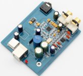
SA9018K2M
This one from aliexpress is a little bigger. First things first,
1. The PCB design is a joke. Whoever made it was in a rush or didn't know what they were doing.
2. the components aren't the best, especially the capacitors which are not ceramic and many hole-through components have been chosen merely to save on a few cents.
3. the audio is being fed into an op-amp to feed the headphone socket and there's some resistance to then feed the phonos. This will colour the sound.
Sound quality wise it's not bad at all. It walks over the TDA5102 with a more acute upper-end and sound-stage. It doesn't however beat the ES9023 (which requires a mandatory op-amp). Perhaps if the PCB had been designed properly and if the op-amp had been used only for the phono then the 9018, as a technically better chip, would take top spot.
Overall then I can place all these USB DAC's in position of superiority:
1. SA9023 (amazing soundstage, presentation, dynamics)
2. SA90182KM (close 2nd)
3. TDA1387 (needs the top-end fixing then could perhaps compete)
4. TDA5102 (poor upper, lack-sure sound stage, bland)
Attachments
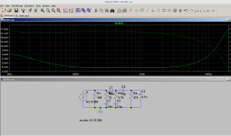
Hi @abraxalito, I have saved the schematic from that blog but it seems incomplete, there are 3 transistors used in the component list and in the schematic I can see only one; I would like to try the Anti-imaging and NOS droop filter, could you tell me what value is R44 and R45, is it in kohm or in ohm? also, what are I20 and I21 representing on the right side?
I imagine these values are for 4 paralelled TDA1387s, do I have to change some value in case of using 8 paralelled TDA's? I was thinking that R46 needs to be changed in this case
An externally hosted image should be here but it was not working when we last tested it.
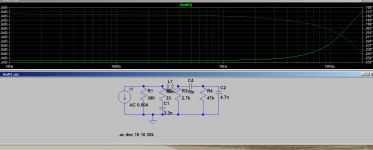
you have also posted another NOS drop filter in another thread, this one was together with some low frequency compensation, which one do you thing is more accurate or appropiate for the real NOS drop? thanks
An externally hosted image should be here but it was not working when we last tested it.
I'm interested in trying out the simpler (second) schematic to give the board another chance. Did you build it for the L1387?
Also I read (may be incorrect) to remove the 2n2 (blue) caps. Why?
If my memory's correct, the second schematic was my attempt at reverse engineering a 'Hat' DAC designed for a RPi. It looked rather like this one (a Chinese clone of the original I think) : ???Raspberry pi2 pi3 B+???DAC TDA1387 8????I2S??-???
As its not my design, I just tweaked it a bit in LTSpice, I didn't try building it.
The 2n2 cap deletion was in another context, the 8*TDA1387 Taobao DAC with opamp output stage. 2n2 being the low pass filter caps around the opamp.
As its not my design, I just tweaked it a bit in LTSpice, I didn't try building it.
The 2n2 cap deletion was in another context, the 8*TDA1387 Taobao DAC with opamp output stage. 2n2 being the low pass filter caps around the opamp.
Thanks for that.
I've since added two more TDA's to the circuit (giving 4). Originally this was way too loud but (oddly) with two new chips it's not too bad. The sound quality is much improved and I think with the droop correction it may be a contender to beat the delta-sigmas I've collected.
As I have way too much volume still I'd rather use a passive filter to sacrifice some of it. Did you tweak it for 4 chips (if necessary)?
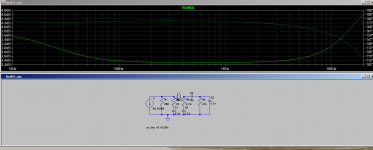
Looks pretty good to me.
What's with the bass correction?
which type choke do you recommend? these ok? Ferrite Cored RF Coil, Leaded RFC Inductor Choke, Inductance Range 100uH to 10mH | eBay
What's with the bass correction?
which type choke do you recommend? these ok? Ferrite Cored RF Coil, Leaded RFC Inductor Choke, Inductance Range 100uH to 10mH | eBay
Attachments
Last edited:
What's the 'it' ('Did you tweak it...') in post#64?
'Bass correction' in the 2nd filter isn't an aim, its just an artifact of how that filter works. Incidentally there's a mistake in the current source, it should be 4mA, not 8mA (for 8 chips).
You should try running the simulation with the 10mH choke you linked to, to see if its acceptable. The key parameter is the DCR (115ohm according to the data).
Re: bass correction, I disabled one of the capacitors and it removed the bass extension without affecting the treble, so to me it looks like it's specifically for that purpose. Are you aware of these chips having a bass deficiency? I recall you saying something about the 20ohm I/V resistor having an effect on bass perhaps its to counteract that?
The original 'Bitstream' S-D DACs had a perceived bass deficiency due I think to noise modulation. More modern multibits I think shouldn't suffer that issue but opamps in general seem to my ears to have inherent bass weakness.
Which D-S DACs have you listened to that exhibit bass weakness?
I dislike D-S DACs for the HF, not the lack of bass. Noisy HF is much more annoying than weak bass.
Which D-S DACs have you listened to that exhibit bass weakness?
I dislike D-S DACs for the HF, not the lack of bass. Noisy HF is much more annoying than weak bass.
Really?!!
Got 'em roughly in 2014 from eBay (China), in a tape-roll strip of several. About $0.99/ea.
They measure well and sound better than my genuine TDA1545A (as expected because 1387 are native I2S).
snoopy33: You'll need to come up with some solid, linked references to prove your case")
Mine look like the "fake" THAILAND in the left image of post #4, and also the putative "genuine" TDA1387 from the Creative board in Post #5.Mine look like the 'fake' ones you've shown, [...] I
Got 'em roughly in 2014 from eBay (China), in a tape-roll strip of several. About $0.99/ea.
They measure well and sound better than my genuine TDA1545A (as expected because 1387 are native I2S).
snoopy33: You'll need to come up with some solid, linked references to prove your case
My first DIY DAC had two DAC chips. One was pcm1704, and the other was pcm1796. Pcm1796 was operated in external digital filter mode which means both can accept the same OSR data. I intended to compare them on the same conditions. I listened to pcm1704 one day and the other day pcm1796. I sometimes felt pcm1796 has weak bass, not always but sometimes. Pcm1704 was always the same bass. My music file is classical music which needs strong bass.
My conclusion was of course pcm1704. I don't know why pcm1796 isn't stable about bass. One possibility I am suspicious is vibration. DSM DACs have internal PLL and Switched Capacitance Filter. They are very sensitive to vibration because they use a variable capacitor whose value depends on the distance between terminals. Vibration can quickly change the distance. Some people say a CD player is also sensitive to vibration like a turntable. I can't say yes or no about that. But some parts are very sensitive to vibration. It's better to take care of PLL and SCF to be free from vibration. Multi-bit DACs usually don't have such circuits.No manufactures do the measurement in a loud room. Their numbers are without vibration.
My conclusion was of course pcm1704. I don't know why pcm1796 isn't stable about bass. One possibility I am suspicious is vibration. DSM DACs have internal PLL and Switched Capacitance Filter. They are very sensitive to vibration because they use a variable capacitor whose value depends on the distance between terminals. Vibration can quickly change the distance. Some people say a CD player is also sensitive to vibration like a turntable. I can't say yes or no about that. But some parts are very sensitive to vibration. It's better to take care of PLL and SCF to be free from vibration. Multi-bit DACs usually don't have such circuits.No manufactures do the measurement in a loud room. Their numbers are without vibration.
Hi abraxalito,Here's the revised *4 DAC schematic as there are component errors in that I put up in post #20. C11 & C12 should be 2.2uF, not 1uF.
Back to the earlier question about oscillations - a filter only rings when its excited and to excite it it needs energy in the input signal close to its resonant frequency. There's not much in audio above 16kHz or so so I reckon the emphasis on ringing is overblown. Your final point se is a good one - there's the upstream AAF to be accounted for at the very least, plus ringing from any EQs that have been employed.
I have put a scope on the output of one of my prototype DACs when playing a sinewave @ 15kHz or so. The usual NOS 'stairsteps' aren't anywhere to be seen but there is a visible modulation of the 15kHz by its first image frequency. I think I posted up a picture before in another thread where this was being discussed.
Could you please share kicad files or similar of the new three stack pcb's?
I'm very curious to build this interesting dac.
Regards,
Yo
- Status
- This old topic is closed. If you want to reopen this topic, contact a moderator using the "Report Post" button.
- Home
- Source & Line
- Digital Line Level
- Impressions: USB DAC: TDA1387 NOS vs PCM5102A Delta-Sigma