Hi Marcelo,
Seemlessly integrating the requested change would be not as easy as you might think.
I will have a look at the possibility, but only after the release of the next update - I have more than enough work to do already.
In the meantime, you can of course always use AkAbak...
Kind regards,
David
Update! Looking forward to the update. I expect it will be interesting.
Hornresp Update 4300-180414
Hi Everyone,
CHANGE 1
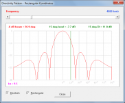
The Directivity Pattern can now show off-axis directivity index values, not just the on-axis value. Attachment 1 refers.
CHANGE 2
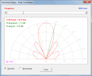
The Directivity Pattern can now be displayed using either polar or rectangular coordinates. Attachment 2 refers.
CHANGE 3
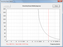
The Directivity Beam Width chart is now generated as a secondary chart rather than as an additional main chart. Attachment 3 refers.
CHANGE 4
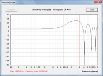
A Directivity Index chart has been added as a secondary chart. Attachment 4 refers.
CHANGE 5
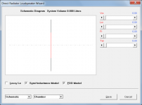
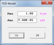
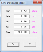
Semi-inductance and frequency-dependent damping (FDD) models have been added.
Double-click the Le text box in edit mode to select the semi-inductance model. A green Le label indicates that the semi-inductance model has been selected.
Double-click the Cms label in edit mode to select the FDD model. A green Cms label indicates that the FDD model has been selected.
My thanks to 'bolserst' for his help during the development and testing of the two new models. Attachments 5, 6 and 7 refer.
NOTES
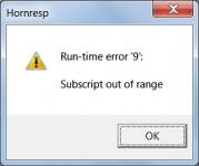
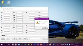
1. Driver parameters copied to the Driver Database using this latest release cannot be pasted into an older version of the program. The fatal run-time error shown in Attachment 8 will occur.
2. Driver parameters copied to the Driver Database using an older version of the program will be automatically updated as necessary when pasted into the latest release.
BUG FIX
The Lossy Le option was not working correctly when used with BP6, BP8 and ABC loudspeaker designs. This has now been fixed. My thanks to 'thejessman' for reporting the problem.
Kind regards,
David
Hi Everyone,
CHANGE 1
The Directivity Pattern can now show off-axis directivity index values, not just the on-axis value. Attachment 1 refers.
CHANGE 2
The Directivity Pattern can now be displayed using either polar or rectangular coordinates. Attachment 2 refers.
CHANGE 3
The Directivity Beam Width chart is now generated as a secondary chart rather than as an additional main chart. Attachment 3 refers.
CHANGE 4
A Directivity Index chart has been added as a secondary chart. Attachment 4 refers.
CHANGE 5
Semi-inductance and frequency-dependent damping (FDD) models have been added.
Double-click the Le text box in edit mode to select the semi-inductance model. A green Le label indicates that the semi-inductance model has been selected.
Double-click the Cms label in edit mode to select the FDD model. A green Cms label indicates that the FDD model has been selected.
My thanks to 'bolserst' for his help during the development and testing of the two new models. Attachments 5, 6 and 7 refer.
NOTES
1. Driver parameters copied to the Driver Database using this latest release cannot be pasted into an older version of the program. The fatal run-time error shown in Attachment 8 will occur.
2. Driver parameters copied to the Driver Database using an older version of the program will be automatically updated as necessary when pasted into the latest release.
BUG FIX
The Lossy Le option was not working correctly when used with BP6, BP8 and ABC loudspeaker designs. This has now been fixed. My thanks to 'thejessman' for reporting the problem.
Kind regards,
David
Attachments
Maybe, there are different ways to implement it, but as you can see in the attached image it wouldn't affect the current interface and all math already exist inside the hornresp.
Hi Marcelo,
If I were to make the change you have requested, it would be implemented quite differently to your suggested method. The advantage would be that you would be able to specify both a rear chamber and a rear flare segment. The potential disadvantage would be that you would be limited to a maximum of three segments for the offset driver horn itself, rather than the current four. Would this be acceptable?
(The OD example you show has four segments, but since all have the same cross-sectional area, only two are really required).
Kind regards,
David
Update! Looking forward to the update. I expect it will be interesting.
Update released. Enjoy
.


Update released. Enjoy
This is going to be interesting.
Thankyou very much both David and Steve (bolserst). The inductance issue has gone from an educated guess via Justaguy's explorations to something that has measurement and mathematical rigour. I like it!
Would this be acceptable?
For sure. For that kind of cab design it will perfectly work. Thanks a lot and thanks for the last update as well

regards,
Marcelo
The potential disadvantage would be that you would be limited to a maximum of three segments for the offset driver horn itself, rather than the current four. Would this be acceptable? /quote]
Hopefully this is implemented as an option. I like having four segments available for an OD horn...
For that kind of cab design it will perfectly work.
Hi Marcelo,
In that case I will start looking at what would need to be done in Hornresp to implement the requested feature.
Kind regards,
David
Hopefully this is implemented as an option. I like having four segments available for an OD horn...
Hi Brian,
You can rest easy, the existing OD option is not going to change. You will still have your four segments to play with
.If all goes according to plan, the configuration requested by Marcelo will be implemented as a compound horn, but with the driver offset in horn 1. Segment 4 will be used for horn 2, as in the standard CH option. The new offset driver compound horn option will be designated as CH1.
Kind regards,
David
Last edited:
It's just to much octane for Hornresp to handle !
I'm getting my head around some of the new toys to. Imagine looking into the manual!
Using this program since the early 2000's what a change.
I can't remember exactly when 2003 or 2004 But I have foggy memories of downloading it in early 2000. Might be right. Might be wrong. Mr. McBean will know when he first put it on the www.
LMAO! I'll try reloading HR on the laptop to see if that cures the problem.
Hi BP1Fanatic,
Try deleting the existing Hornresp.dat file from your laptop before running Hornresp. Indications are that the data file has been corrupted.
Alternatively, try copying your existing desktop Hornresp.dat file to your laptop (overwriting the existing laptop file).
Kind regards,
David
Last edited:
Very minor usability suggestion to save my clicking the same slider many times
change the default Q factor in the filter wizard from 0.01 to a more reasonable default. A sane default probably varies by filter type but I would guess ~0.7 is a reasonable default for shelf filters and high/low pass.
... or critical damped - Q=0,5.
//
... or critical damped - Q=0,5.
Hi TNT,
The default Q value is not going to change
.Quickly setting the desired slider value should not be a problem - see my Post #8200.
In summary:
1. Click on the slider (so that it has the focus)
2. Type 0,5
3. Press Enter
Job done.
Kind regards,
David
Hi David,
43.00
Wanting to compute a simple vented box, here's my driver file (hand crafted):
RCF L18P400
Sd=1220.00
Bl=24.2
Mmd=200
Le=2.50
Re=5.10
Pmax=1000
Xmax=9.0
LossyLe=0
Qes=0.29
Qms=7.6
Qts=0.28
Vas=340
fs=29
Following your recommendation...
> Select the 'Rear Vented' option from the Chamber Type tool and set S1 to L45 = 0 and Vrc, Lrc, Ap and Lpt > 0.
However, after pasting the driver into the record I got "Invalid result. Change input data."
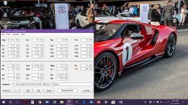
Double clicking on Le showed the following values in the Semi-Inductance Model window: RE', Leb, Le and Ke all filled in, but the Rss field empty. Clicking the Off button said "Rss must be a number between 0,00 and 99999,99."
After entering a zero in Rss field all went well.
This is just FYI. If it is meaningful then you may want to code in that default.
Thanks,
Andre
BTW: the RCF T/S params are missing Cms and Rms - does that hurt anything?
43.00
Wanting to compute a simple vented box, here's my driver file (hand crafted):
RCF L18P400
Sd=1220.00
Bl=24.2
Mmd=200
Le=2.50
Re=5.10
Pmax=1000
Xmax=9.0
LossyLe=0
Qes=0.29
Qms=7.6
Qts=0.28
Vas=340
fs=29
Following your recommendation...
> Select the 'Rear Vented' option from the Chamber Type tool and set S1 to L45 = 0 and Vrc, Lrc, Ap and Lpt > 0.
However, after pasting the driver into the record I got "Invalid result. Change input data."
Double clicking on Le showed the following values in the Semi-Inductance Model window: RE', Leb, Le and Ke all filled in, but the Rss field empty. Clicking the Off button said "Rss must be a number between 0,00 and 99999,99."
After entering a zero in Rss field all went well.
This is just FYI. If it is meaningful then you may want to code in that default.
Thanks,
Andre
BTW: the RCF T/S params are missing Cms and Rms - does that hurt anything?
- Home
- Loudspeakers
- Subwoofers
- Hornresp