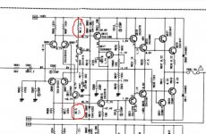
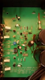
The numbers are to blurred in my scanned copy to be certain but they are the two transistors that the series diodes connect to. The emitters go to R614 and R616, those two")
Ok checked all transistors except Q610 and Q612
OK, so lets try and put some more numbers into this to see what's going on because the readings don't tally with what should be happening.
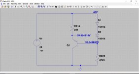
You are looking at the top current source only for now. This shows the typical voltages for a 40 volt rail and a 15 volt rail.
Do you see the same relationship in the voltages ? The diode volt drops are similar, and the voltage over the resistor is similar.
Your diode voltages are good and yet you say you have 2.65 volts across the resistor R614. That 2.65 volts would place the emitter at a lower voltage than the base.
We know the base must be correct because you measured 0.65 volts across each diode. So if you subtract 1.3 volts (the two diodes) from your measured supply voltage then you should that voltage from real on the base.
Similarly for the emitter. If you subtract the volt drop across R614 from the supply you will get the emitter voltage.
Those are two checks worth doing to confirm the validity of your previous measurements.
Also, the base/emitter voltage should be around 0.6 to 0.7 volts.
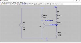
Attachments
Fixed it - thanks to all
Q621: 2SA1376
Q619: 2SC3478
Replaced with ebay transistors from ebay. I know I should not have but just wanted to get it working. I can now adjust the bias on both sides. Previous blown left hand side has 168mv and right has 68mv.
I am so glad I managed to do it. I should have taken my time to study things more carefully instead of diving in to change parts!.
Not sure if I want to risk it with my speakers but project objectives have been achieved.
What can I do about the 168mv dc????
Good to hear you have had success with this.
Offset... hmmm 168mv is pretty high in absolute terms although it will do zero damage to a speaker. I haven't got the diagram in front of me but the two things that would influence this are imbalance in the front end input stage (the four transistors need to be reasonably matched along with their tail currents).
Beyond that and a scope check for low level oscillation would be advisable. There is nothing else really that would cause the offset.
Offset... hmmm
168mv is pretty high in absolute terms although it will do zero damage to a speaker. I haven't got the diagram in front of me but the two things that would influence this are imbalance in the front end input stage (the four transistors need to be reasonably matched along with their tail currents). Beyond that and a scope check for low level oscillation would be advisable. There is nothing else really that would cause the offset.
Tried the amp with some throw away speakers and it appears to work well
Would reducing the values of R623 and / or R603 be useful in reducing DC? While I ws messing about on this journey and making errors I put a 1.21K ohm resistor instead of 100ohms into the R623 slot and found that DC shot up. Similarly touching the R603 causes the DC to shoot up as well?
Good Idea / Bad Idea?
The key to good DC balance lies in good matching of the transistors in the input stage.
You could try altering the balance of these. Increase or decrease one slightly and if needed do the opposite to the other one. That will certainly trim the offset but it is not the proper way to do it.
You could try altering the balance of these. Increase or decrease one slightly and if needed do the opposite to the other one. That will certainly trim the offset but it is not the proper way to do it.
Attachments
Which transistors would need to be checked for the input stage?
The two sets of long tailed pairs (the left hand four transistors). You could try swapping the two in a pair over and see if that gives a lower offset. If it does then see if it can be improved again by swapping the other pair as well.
Project Completed (I hope)
Hi All
Decided to stop messing with it for now (!) as Jaycee suggested and start using it as the garage stereo with my Wharefedale Diamond II's from the 80's. Will live with the 148mv dc on the repaired side. I did use matched pairs of transistors from RS components.
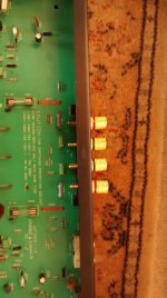
I also fitted replacement speaker terminals as the existing ones were broken.
Next project is a JBL home cinema Xcite 360 with blown large resistors from my father in law. A new thread!
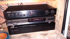
Can anyone suggest a cheap control amp to buy from ebay to use with the rotel. I have a rotel RC970 but am using it with the other RB970
Hi All
Decided to stop messing with it for now (!) as Jaycee suggested and start using it as the garage stereo with my Wharefedale Diamond II's from the 80's. Will live with the 148mv dc on the repaired side. I did use matched pairs of transistors from RS components.
I also fitted replacement speaker terminals as the existing ones were broken.
Next project is a JBL home cinema Xcite 360 with blown large resistors from my father in law. A new thread!
Can anyone suggest a cheap control amp to buy from ebay to use with the rotel. I have a rotel RC970 but am using it with the other RB970
Attachments

That all sounds like a good result then
(I think you will find the transistors need to be matched not just in pairs but also in complentary pairs i.e NPN/PNP)
Hi Mooly. Just out of interest...
I actually changed one of the two a pairs of power transistors on the right hand side as well beacuse I had them but left the other pair insitu as you have to remove the whole board from the heatsinks to repalce that second pair and it made no difference to the DC.
I think unless something else goes wrong I will live with it for now. It has been running for 5 hours now in the garage and still lives!
- Status
- This old topic is closed. If you want to reopen this topic, contact a moderator using the "Report Post" button.
- Home
- Amplifiers
- Solid State
- Rotel 970 BX Repair