No, they are too low power for the VAS circuit in the Rotel amp.
I think the best thing to do if you are sure the VAS transistors have failed, is order some KSA1381/KSC3503 transistors. Farnell UK have them (code 2453937 and 2453937). These are going to be the best replacements you can get.
I am assuming that I will have to order in pairs even though the 2SA1208s are OK?
I am assuming that I will have to order in pairs even though the 2SA1208s are OK?
Yes, I would advise replacing both pairs with matching types, due to the topology of the circuit.
KSC3503DS = 2453955, hFE 60-120
KSA1381ESTU = 2453937, hFE 100-200
Note that the KSC3503 suffix is 'D" and the KSA1381 suffix is 'E' so they are from different hFE brackets. Gain matching will likely not be possible. KSC3503E is not available nor is KSA1381D. Why the manufacturer only offers mismatched gain sorting for these complementary devices is a question for the ages...
KSC3503DS = 2453955, hFE 60-120
KSA1381ESTU = 2453937, hFE 100-200
Note that the KSC3503 suffix is 'D" and the KSA1381 suffix is 'E' so they are from different hFE brackets. Gain matching will likely not be possible. KSC3503E is not available nor is KSA1381D. Why the manufacturer only offers mismatched gain sorting for these complementary devices is a question for the ages...
Yes, it's a pain.. but they are the most readily available suitable VAS transistors at this point!
Yes, it's a pain.. but they are the most readily available suitable VAS transistors at this point!
Hi,
I have some of them, and it's not as bad as it looks. I found pairs around Hfe=110.
Sajti
You do need to be very sure you have the correct value parts in all the right locations. Its also important to make sure you haven't mixed any NPN devices for PNP and vice versa.
Non adjustable bias on the right channel... the first thing is to put your meter across Q618 and see what the voltage varies between as you turn the preset.
You need to overcome all the 'base-emitter' volt drops of the predrivers, drivers and outputs before the output stage draws current which means somewhere around 3.5 to 4 volts is needed.
Q617 burning on the left channel can only be because of failed or incorrect/incorrectly fitted pre drivers. There is no other possible low impedance path present that could deliver a damaging current.
It is possible however that the driver and outputs could be faulty/incorrect/incorrectly fitted and that these have caused failure of the pre drivers.
0 Volts across Q618 but Q618 working (removed and tested).
Q620 / Q622 also OK. Working my way across the right hand channel transistors.
Any ideas?
Last edited:
No voltage across Q618 suggest that no current is flowing in Q614 and 616.
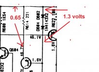
Check that each series diode array has around 1.3 volts across them and also that there is around 0.65 volts across R616 and R614.
Check that R622 and R624 are OK.
All diodes have 20 - 40 volts and most resistors are reading 0 volts. Could it be the caps?
Last edited:
Something very amiss there. The diodes can not support more than around 0.7 volts each (so 1.4 total). If there really is 20 to 40 volts across them then not only are the diodes open circuit, but so to R614 and R616.
I would recheck those results. You are looking for around 1.3 volts across each pair.
I would recheck those results. You are looking for around 1.3 volts across each pair.
Attachments
")
No voltage across Q618 suggest that no current is flowing in Q614 and 616.
Check that each series diode array has around 1.3 volts across them and also that there is around 0.65 volts across R616 and R614.
Check that R622 and R624 are OK.
D602 nd D604 are around 0.657 volts each
R616 = 0 volts
R614 = 2.65 volts
The diode reading is good.
You should also see the same result for diodes D606 and D608.
The resistor voltages are showing a big problem. The first thing to check is that the two transistors are good, that the pinout is correct, and that you haven't mixed NPN for PNP.
The two diodes, the transistor and the resistor form a basic current source. You should always see around 0.65 volts between base and emitter (base positive with respect to emitter for the NPN and vice versa for the PNP) and the resistor should always see around the same voltage, about 0.65
Look at figures 4, 5 and 6 here. In your case the two diodes form the reference voltage.
Current source - Wikipedia
- Status
- This old topic is closed. If you want to reopen this topic, contact a moderator using the "Report Post" button.
- Home
- Amplifiers
- Solid State
- Rotel 970 BX Repair