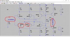
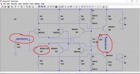
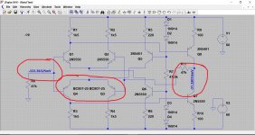
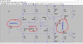
This is a similar front end from an old simulation. Look at the offset voltage and its polarity as the transistors are changed in just one of the pairs. In simulation, any device of the same number is identical to every other of the same type. 100% matched in every possible way.
Ideally this amp needs a manual method of tweaking the offset or a DC servo adding.
Ideally this amp needs a manual method of tweaking the offset or a DC servo adding.
Attachments
Hi All
Decided to stop messing with it for now (!) as Jaycee suggested and start using it as the garage stereo with my Wharefedale Diamond II's from the 80's. Will live with the 148mv dc on the repaired side. I did use matched pairs of transistors from RS components.
I also fitted replacement speaker terminals as the existing ones were broken.
Next project is a JBL home cinema Xcite 360 with blown large resistors from my father in law. A new thread!
Can anyone suggest a cheap control amp to buy from ebay to use with the rotel. I have a rotel RC970 but am using it with the other RB970
Hi ssi,
well done, they both work again !! Congrats
according to the manual you can use this amplifier as bridged mono amplfier with 180W/8 Ohm output power. This is only valid, if the connect speaker are > 8Ohms. Do not connect speakers with <8 Ohms in bridged mode. Try to find the operation manual for the RB-970BX on the net for more detailed informations.
BR
Günni
Hi
The pair I had used had only 1mv between them so this may be the best I can do.
You would be looking to match the forward current gains at the current values seen in operation in the actual circuit... its not easy, and its very time consuming.
")
May change 2SA1208 + 2SC2910 as they were next in line for failure after
Q621: 2SA1376
Q619: 2SC3478
from the original very burned resistors.
They seem to be getting quite warm comapared to the right hand channel. Only £3 for 2 pairs from China from the seller I purchased Q621/619. They specialise in audio and have 99.8% rating from 27K sales so happy to risk it for this project.
If they are getting warmer than the other channel then that suggests either the DC conditions are incorrect or there is oscillation.
Make sure the DC voltage is the same across R621 and R623, and that the voltages are the same between channels. You should see around 1.2 volts across each, with each transistor dissipating around 700mW.
Also make sure those two resistor values are correct. If you have replaced them then check they are the same value as fitted to the good channel.
If the voltages agree and the resistor values agree then any temperature difference is down to either perceived differences or differences due to physical layout with one side seeing better airflow and cooling. W=I*V and so if those values are the same between channels then the heat produced is the same as well... instability and oscillation excepted.
Changing transistors based on a suspicion that they may be partly damaged is not a good idea. In virtually all cases of properly designed circuits, small signal transistors either remain 99.9% OK or they are toast in the blink of an eye. Unlike large resistors or electromechanical devices, there can be no middle ground when failures occur in milliseconds. Sure, there have been some manufacturing design flaws that resulted in gradual failure of certain small signal transistors but they are well known to service people.May change 2SA1208 + 2SC2910 as they were next in line for failure after
Q621: 2SA1376
Q619: 2SC3478
from the original very burned resistors......
The two sets of long tailed pairs (the left hand four transistors). You could try swapping the two in a pair over and see if that gives a lower offset. If it does then see if it can be improved again by swapping the other pair as well.
Mooly, what do you mean by this? Which Q's?
- Status
- This old topic is closed. If you want to reopen this topic, contact a moderator using the "Report Post" button.
- Home
- Amplifiers
- Solid State
- Rotel 970 BX Repair