Hello WrineX.
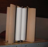
The reel is wound on a mandrel with taped tape "scotch" (pictured).
In the center of the coil paper ,is used to create a gap.
Each 3-5 turns are fixed with glue BF.
The coil is removed from the mandrel and coated with glue not glued areas.
If you want to cut the center paper (to reduce the weight)
The reel is wound on a mandrel with taped tape "scotch" (pictured).
In the center of the coil paper ,is used to create a gap.
Each 3-5 turns are fixed with glue BF.
The coil is removed from the mandrel and coated with glue not glued areas.
If you want to cut the center paper (to reduce the weight)
Last edited:
Hello Guys,
I’m following your thread for 2years. I decided to make a ruba. This winter I finally started the project.
- 40 pcs Chinese ali magnets 40x20x10 (39x19x9.6) with holes fixed with screws
- S235 45cmx10mm steel bars
For coil I’d like to use 30um alu tape cutted with vinyl cutter knife on DIY cnc. My friend is playing with his machine try to cut the alu tape (knife from ali too).
I can’t wait longer and I make a coil with 0.28 mm diameter copper wire. 14 turns x 2 coils connected serial. Resistance 7.8 ohm. Glued with epoxy to Canson paper. Weights 48 gramm. (1 empty sheet 125g/m 15.6g calculated, measured 16g). So it became heavy. At least I heard ruba playing today.,
No surprise, there is no highs. Low freq response is quite flat. (it has more bass then my 4” fullrange closed box)
I have big resonances at 115Hz and above. (double, 3rd etc.)It is visible, audible and the distortion chart shows them.
Do you have idea why I have this huge vibration/distortion, how to avoid?
Those resonant peaks are a succession often seen in metal cones above the first breakup mode. The twin tubes plus the voice coil in your structure are very stiff ( along their length)and likley not well damped in the region of trouble.
Many years ago I was working on a open baffle bass diaphragm that used the exact same VC design as you have there. I called it the "over and under" VC. It was stiff! BUT when you made it long (in my case about 35 inches) it had all sorts of resonant issues.
In the end to get acceptable perf I actually corrugated the VC , AND slit the diaphragm about every 75 mm so that it was a bunch of much shorter structures . The result was smoother response.

Something I'm curious about... is this project worth pursuing just for the sake of the spatial characteristics of the sound, or is sensitivity what we're after? I have bigger amps than I need. Based on a video Wrine posted way back of a wider foam board ruban, I'm wondering if full range might be achievable with easier construction at the expense of lower sensitivity.
Hello ALTIE.
The Rubanoid does not sound like ordinary speakers.
With the support of the bass, it's a complete acoustic system.
They need to be heard once.
Without the support of bass, very good shelf acoustics.
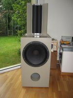
I use Rubanoid only with the support of 12" bass and tape tweeter at the very top.
The Rubanoid does not sound like ordinary speakers.
With the support of the bass, it's a complete acoustic system.
They need to be heard once.
Without the support of bass, very good shelf acoustics.
I use Rubanoid only with the support of 12" bass and tape tweeter at the very top.
Last edited:
Something I'm curious about... is this project worth pursuing just for the sake of the spatial characteristics of the sound, or is sensitivity what we're after? I have bigger amps than I need. Based on a video Wrine posted way back of a wider foam board ruban, I'm wondering if full range might be achievable with easier construction at the expense of lower sensitivity.
Actually we are looking for everything (new materials, new techniques and ideeas).
You can make a bass ruban with a classic magnetic motor coupled with an almost fullrange ruban but never a fullrange ruban with a plane coil. Maybe a classic cilinder coil can do fullrange with some tricks aded to the membrane, who knows.. (Like in the articles from 1927 that i posted above earlier with an almost flat membrane like Wrine's and a classic motor with classic coil and a semi-hard spider). May get really cheaper that way and, maybe, fullrange.
Cheers
2nd trial
Hello,
I made a 2nd membrane:
Xerox never tear 95 um 125g/m2, 0.17mm single coil 11 turns 8 ohm DC resistance.
I used 20 min epoxy instead of 5 min. Last time 5 min start to set before i finished completely.
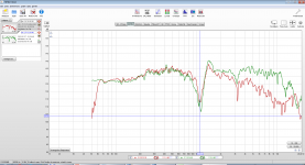
Freq. response is improved it goes little above 10 kHz. (red graph is canson paper with heavy double coil, green is the lighter membrane)
Unfortunately the resonance/distortion around 120 Hz is still there and kills the sound.
Seems the problem was not the improper gluing with epoxy. (or maybe i do it similarly wrong even I did it with much more care and slower epoxy)
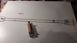
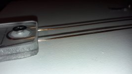
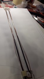
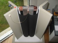
Procedure how I made:
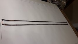
I wind he wire in a jig, fixed 4 places with super glue.
Then glue the wires at each 4-5 cm with small super glue dots to membrane.
Then apply epoxy on the wires compete surface of wires, and put the other side of membrane on it with weights, wait 24 hours.
See pictures, for better understanding.
Hello,
I made a 2nd membrane:
Xerox never tear 95 um 125g/m2, 0.17mm single coil 11 turns 8 ohm DC resistance.
I used 20 min epoxy instead of 5 min. Last time 5 min start to set before i finished completely.
Freq. response is improved it goes little above 10 kHz. (red graph is canson paper with heavy double coil, green is the lighter membrane)
Unfortunately the resonance/distortion around 120 Hz is still there and kills the sound.
Seems the problem was not the improper gluing with epoxy. (or maybe i do it similarly wrong even I did it with much more care and slower epoxy)
Procedure how I made:
I wind he wire in a jig, fixed 4 places with super glue.
Then glue the wires at each 4-5 cm with small super glue dots to membrane.
Then apply epoxy on the wires compete surface of wires, and put the other side of membrane on it with weights, wait 24 hours.
See pictures, for better understanding.
Attachments
Borzi you cannot go fullrange with this speaker with plane coil and that lightweight membrane. The only way is to use it at low volume levels. Another way is with heavier membrane, lets say like 250-300gr paper or heavier but this way you will have to make another ruba for the upper frequency, so a two way result.... This is because between 110-150hz is like the breaking point for the membrane with this material and plane coil. From here bellow, the coil starts to move heavily and needs ro be rigid amd inside the gap. You can try changing the shape of the membrane from cilinders to an open book like in the pics from 1925 or a plane shape like Wrine's ideea from youtube.
Another ideea, if you want to go fullrange offcourse, is to dissasemble an old speaker, and use the motor and spider and atach an ruban like membrane to the coil and start from there..
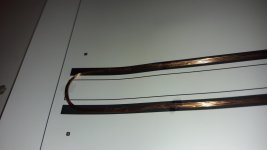
Another thing you can do to improve the hights with your copper winded coil is to let the round edges of the coil outside the membrane because its adding mass to the coil region. And i recomend to do this because, bassically that portion is outside the gap and can be heathing (another important aspect ) and change impedance to a point that it can make a bit of mess from a part of your frequency graph. If you cut that membrane portion (top and bottom) cutt it to bellow the round shape till where the coil is straight.
Cheers
Ps: as me and Wrine didnt test the wirewound copper coil i have to ask you to please post everything you try and discovered (even if its good or bad) as we did because it may help other allot.
Thanks
Another ideea, if you want to go fullrange offcourse, is to dissasemble an old speaker, and use the motor and spider and atach an ruban like membrane to the coil and start from there..
Another thing you can do to improve the hights with your copper winded coil is to let the round edges of the coil outside the membrane because its adding mass to the coil region. And i recomend to do this because, bassically that portion is outside the gap and can be heathing (another important aspect ) and change impedance to a point that it can make a bit of mess from a part of your frequency graph. If you cut that membrane portion (top and bottom) cutt it to bellow the round shape till where the coil is straight.
Cheers
Ps: as me and Wrine didnt test the wirewound copper coil i have to ask you to please post everything you try and discovered (even if its good or bad) as we did because it may help other allot.
Thanks
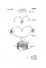
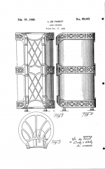
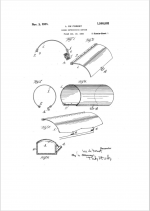
Here is the original ruba right from its times.. They are very usefull. I just found them on a blog.
I published several years ago elsewhere on the internet several other original examples on constraint diaphragms with a tangential ribbon or coil.
The first who introduced these diaphragms was De Forest USD69443 (Audalion) and US 1866090. Below are the first page of both patents !...
Hope this is of some interest.
Best.
PS : Here you'll find a picture of the commercial Audalion Electronic Fossil | Speakers
Attachments
Last edited:
...stumbling backwards in the future....
....this all looks somewhat familiar....*G* Esp. 'Olivier_2307' which has been on my desktop(s) nearly forever....
Happy New Year, y'all...esp. WrineX, 5's guy....")
Although still a Walsh addict, the Lineum dipoles still fascinate this immoral mortal...have a pair of ancient RadShack dipoles on shelf as proof (one lives, one not so much....truth be told, all dipole, omni, planar, and other esoteria of that ilk....), so I'm happy to stumble into this locale....
One query to settle the curiosity of yours truly:
Can the membranes be other than fabric, plastics, or paper; as in alum or titanium?
....this all looks somewhat familiar....*G* Esp. 'Olivier_2307' which has been on my desktop(s) nearly forever....
Happy New Year, y'all...esp. WrineX, 5's guy....
Although still a Walsh addict, the Lineum dipoles still fascinate this immoral mortal...have a pair of ancient RadShack dipoles on shelf as proof (one lives, one not so much....truth be told, all dipole, omni, planar, and other esoteria of that ilk....), so I'm happy to stumble into this locale....
One query to settle the curiosity of yours truly:
Can the membranes be other than fabric, plastics, or paper; as in alum or titanium?
Attachments
...but Reality is still 'conceptual'....Still Under Construction...
...the earlier posted pics of the Really Large versions remind me of the Walsh patents' statement of creating versions for auditoriums, stadiums, and other large venues....
...visions of cones the size of 55g. drums....magnets the size of tire rims....voice coils large enough to swallow small mammals....
"Well, Bert....*sigh*...It looks like your Krell amp just couldn't cope...*fanning away the acrid smoke, still hanging after the fire department doused everything in the listening room*..."
Hello.
Made a membrane of paper Palazzo (for pastels) 160gr \ m 40% cotton.
It sounds a bit quieter than 120 gr / m usual white.
But the sound is much more interesting, cleaner.
Tried to find 120 gr \ m with cotton, until unsuccessfully.
I also make the lead wires from Litcendrat (15 conductors) in a silk shell.


sergiu2009 what filter did you do?
I cut Ruban only from below 500 Hz.
Made a membrane of paper Palazzo (for pastels) 160gr \ m 40% cotton.
It sounds a bit quieter than 120 gr / m usual white.
But the sound is much more interesting, cleaner.
Tried to find 120 gr \ m with cotton, until unsuccessfully.
I also make the lead wires from Litcendrat (15 conductors) in a silk shell.
sergiu2009 what filter did you do?
I cut Ruban only from below 500 Hz.
Last edited:
Hi Oleg. Thanks for sharing. Indeed an 120gr paper will be interesting..
Did someone find rice or washy paper at 120gr?
Oleg for my tests i used a first order butterworth (basically a single cap summing multiple caps in a total of 66uF), wich translates in about 300hz cutpoint.
Now i'm using a second order butterworth crossed at aprox 220hz but finetuned to smoothout the peak from the crossing region.. Basically the aprox vallues are 8.2uH coils+66uF caps. And ofcourse i altered the caps values to my tastes and needs.
Oleg please try a higher quantity/ratio of cottone. Usually a higher density of fiber paper will sound even more interesting and better defined than regular paper.
Another important aspect is that you should sandwich the coil between the finest face of the paper sheets and respect the orientation of the fibers (horizontally oriented) to get the best results.
Another important aspect is that you should sandwich the coil between the finest face of the paper sheets and respect the orientation of the fibers (horizontally oriented) to get the best results.
- Home
- Loudspeakers
- Planars & Exotics
- A DIY Ribbon Speaker of a different Kind