Use 6N23P/6N23P-EB cards. If needed, adjust the test voltages.
Hello!
Anyone have the E88CC card, or I can stick with the 6N23P – 6Н23П coming with the tester?
Thanks in advance!
Hi,
here is crossreference table of soviet/Russian tubes numbers to European/US numbers.
http://www.misael.cz/user/documents/p%C5%99ev_tab_rus_el_kur.pdf
It it help someone.
here is crossreference table of soviet/Russian tubes numbers to European/US numbers.
http://www.misael.cz/user/documents/p%C5%99ev_tab_rus_el_kur.pdf
It it help someone.
L1-3
Hello!
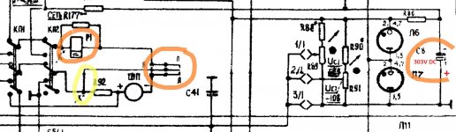
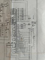
I bought good looking L1-3, but have problem. When pushing button CETb, there is tiny (none) movement of indicator. Pushing KAL button moves indicator needle "over the corner". My questions are: 1) Is it OK that there is 303V DC on C8 with plus to ground? 2) What is yelow marked "K" on wiring diagram? 3) Red marked is relay and its contacts? How should work that circuit?
Thank you for any ideas.
Hello!
I bought good looking L1-3, but have problem. When pushing button CETb, there is tiny (none) movement of indicator. Pushing KAL button moves indicator needle "over the corner". My questions are: 1) Is it OK that there is 303V DC on C8 with plus to ground? 2) What is yelow marked "K" on wiring diagram? 3) Red marked is relay and its contacts? How should work that circuit?
Thank you for any ideas.
Attachments
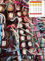
I have similar problem... Except my meter dont move at all... Nothing. Have anyone recomendation where to search for the problem? I suspect el-caps for the smoothing anode.... If so... Are all el-caps in front for the Ua? Left side audio bord, right side power board senter Tr and in front big line of elektrolits.
Meter itself is working and all tubes working... Even for testing tubes.. Heter is working.
I can make high res pictures or video because my model :1986 is slightly different than from schematics on german site.
Meter itself is working and all tubes working... Even for testing tubes.. Heter is working.
I can make high res pictures or video because my model :1986 is slightly different than from schematics on german site.
Last edited:
Can't get the L3-3 to work
Well, I was unlucky to buy a claimed "NOS" and "extra tested" L3-3. It arrived safely with the complete set of cards and accessories.
I asked for help on this post, but was unlucky to grab any attention. Hopefully there is some L3-3 experienced user who may help here!
http://www.diyaudio.com/forums/equipment-tools/238590-problem-new-l3-3-please-help-2.html
I made the following changes:
1. Re-tested all valves and changed the ones measuring low. I ordered new ones as have some 6N3P unmatched sections (V18). This could the reason why I can't calibrate the uA voltmeter given the mismatch between triodes.
2. The Ug1 pots changed to 10T wirewound
3. The Ua and Ug2 pots changed to new 1Meg ones.
I tested all valves per manual and the voltages are ok. I re-calibrated the transconductance meter and struggled to get the 450mV reference. The voltage drops quickly from 500mV down to 20-50mV when adjusting R157. The frequency was set to 1400Hz and voltage left to 500mV. It seems to work fine.
The filament supplies are ok. I can set grid voltages accurately, however there is a load impact when switching from "Ug1" to "Ia". For example, I was testing a CX301a and set the voltage to -9V in "Ug1" that changed (measured at the grid with external voltmeter) to -8.8V.
So what is not working:
1. I can't measure the Ua on the meter. It sounds like a bad contact on the rotary switch. Any tips for dismantling it and cleaning it? It seems like a complex stuff. Im scared with the amount of connections and whether I could bring all the wafers together again!
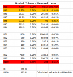
2. The anode shunt resistors are out of tolerance (>0.2%). I found 2 measuring out of 0.2% - R50 (4R889) and R46 (97R78). I contacted the seller to see if he can send me them. When measuring a CX301a traced with the Utracer V3, transconductance was very close, however the Ia measurement was way off. This led to investigate and found the resistor drift issue.
3. The screen current resistors are within tolerance (<0.2%). However, when following the screen current calibration/test from the manual (e.g. I used a variable CCS as an external load with a series precision current meter) the meter goes into full scale regardless on the range. Something is wrong here
4. The meter seems to be working fine. Although is not the originally specified meter it has 745R impedance but the R100 measures differently from what it should be. However, the meter seems accurate when measuring Mains, 250V and Us. Also the transconductance values are ok when tested some sample valves. This is leading me to suspect that R100 was chosen to match the actual impedance of the meter in place.
Frustrated, seems to be a long process to hopefully restore this beauty of tester.
Hope any folks out there can give me some advice
cheers
Ale
Well, I was unlucky to buy a claimed "NOS" and "extra tested" L3-3. It arrived safely with the complete set of cards and accessories.
I asked for help on this post, but was unlucky to grab any attention. Hopefully there is some L3-3 experienced user who may help here!
http://www.diyaudio.com/forums/equipment-tools/238590-problem-new-l3-3-please-help-2.html
I made the following changes:
1. Re-tested all valves and changed the ones measuring low. I ordered new ones as have some 6N3P unmatched sections (V18). This could the reason why I can't calibrate the uA voltmeter given the mismatch between triodes.
2. The Ug1 pots changed to 10T wirewound
3. The Ua and Ug2 pots changed to new 1Meg ones.
I tested all valves per manual and the voltages are ok. I re-calibrated the transconductance meter and struggled to get the 450mV reference. The voltage drops quickly from 500mV down to 20-50mV when adjusting R157. The frequency was set to 1400Hz and voltage left to 500mV. It seems to work fine.
The filament supplies are ok. I can set grid voltages accurately, however there is a load impact when switching from "Ug1" to "Ia". For example, I was testing a CX301a and set the voltage to -9V in "Ug1" that changed (measured at the grid with external voltmeter) to -8.8V.
So what is not working:
1. I can't measure the Ua on the meter. It sounds like a bad contact on the rotary switch. Any tips for dismantling it and cleaning it? It seems like a complex stuff. Im scared with the amount of connections and whether I could bring all the wafers together again!
2. The anode shunt resistors are out of tolerance (>0.2%). I found 2 measuring out of 0.2% - R50 (4R889) and R46 (97R78). I contacted the seller to see if he can send me them. When measuring a CX301a traced with the Utracer V3, transconductance was very close, however the Ia measurement was way off. This led to investigate and found the resistor drift issue.
3. The screen current resistors are within tolerance (<0.2%). However, when following the screen current calibration/test from the manual (e.g. I used a variable CCS as an external load with a series precision current meter) the meter goes into full scale regardless on the range. Something is wrong here
4. The meter seems to be working fine. Although is not the originally specified meter it has 745R impedance but the R100 measures differently from what it should be. However, the meter seems accurate when measuring Mains, 250V and Us. Also the transconductance values are ok when tested some sample valves. This is leading me to suspect that R100 was chosen to match the actual impedance of the meter in place.
Frustrated, seems to be a long process to hopefully restore this beauty of tester.
Hope any folks out there can give me some advice
cheers
Ale
Attachments
Last edited:
Hi mogliaa,
For 3. above in things that aren't working, the CCS you are using should set the current limit. So that piece of stuff isn't working. In a series circuit, the component that allows the least amount of current to pass sets the current through that entire circuit. If you are using a FET is some kind, it's probably in backwards.
For 4. above. The series resistor is probably selected to make all the meters have the same total impedance.
1. I wouldn't if at all possible.
2. Yes, probably resistors have drifted out of tolerance.
Fix everything you can find a problem with, then assess your tester again.
-Chris
Thanks for the feedback. The CCS works fine. I also tested with a load resistor and had same result.
I will put the rotary switches in an ultrasonic bath to clean them up as suggested by other fellow.
Does anyone can recommend any acid solution to clean these old switches?
Thanks
Ale
I will put the rotary switches in an ultrasonic bath to clean them up as suggested by other fellow.
Does anyone can recommend any acid solution to clean these old switches?
Thanks
Ale
A wile ago I asked help here..but nothing..so after i decided to restore entire device..
I "fix it" quite fast. All measurement for U and I wore ok until i come to calibrate S.
The needle was twitching and ask around what could be. It was suggested C15 and C31 (PIO).
I measured all caps and resistors and those wore ok... thow i couldn't test for capacitors leakage.
Today I was measuring on scope intern 250 and some other ripples and by strange coincidence S was working .. and 20min after not any more.. so i slader entire audio board again...and it is working.
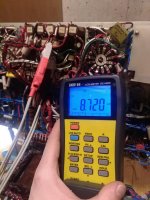
moglia : R100 + ..is kind of tricky ...in my was 490ohm... there is about 10 different impedances for analog meter...
P+R100+R101+R92 = 8720ohm
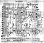
There are several resistors which are diffrent than in book.
Do you have original book?
I make new schematics in autocad (more than 3 weeks of work)..and now i make report with excel tables itc. As soon as I finish I will upload for all.
I "fix it" quite fast. All measurement for U and I wore ok until i come to calibrate S.
The needle was twitching and ask around what could be. It was suggested C15 and C31 (PIO).
I measured all caps and resistors and those wore ok... thow i couldn't test for capacitors leakage.
Today I was measuring on scope intern 250 and some other ripples and by strange coincidence S was working .. and 20min after not any more.. so i slader entire audio board again...and it is working.
moglia : R100 + ..is kind of tricky ...in my was 490ohm... there is about 10 different impedances for analog meter...
P+R100+R101+R92 = 8720ohm
There are several resistors which are diffrent than in book.
Do you have original book?
I make new schematics in autocad (more than 3 weeks of work)..and now i make report with excel tables itc. As soon as I finish I will upload for all.
Attachments
") .... My pretious
.... My pretious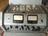
I have check again in book and original schematics and opened the meter and compere between the 3. It is correct. One Russian person said same as you.. but we wore on facebook and check together.
It looks different versions.. my is 1986 with 2 fuses (my original schematics shows only 1).
It looks different versions.. my is 1986 with 2 fuses (my original schematics shows only 1).
Attachments
- Home
- Design & Build
- Equipment & Tools
- Russian L3-3 tube tester