I found the Intusoft SPICE model files from 1987, here is the 2N3055,
I've not looked at it in any detail or compared it to any other versions:
.MODEL QN3055 NPN(IS=1.5E-8 NF=1.67 BF=75 VAF=100 IKF=4
+ BR=4 RC=.06 MJC=.45 VJE=1.2 MJE=.5 XTB=1.5
+ CJE=520PF TF=40E-9 CJC=380PF TR=.8U)
* Motorola Power Transistor
I've not looked at it in any detail or compared it to any other versions:
.MODEL QN3055 NPN(IS=1.5E-8 NF=1.67 BF=75 VAF=100 IKF=4
+ BR=4 RC=.06 MJC=.45 VJE=1.2 MJE=.5 XTB=1.5
+ CJE=520PF TF=40E-9 CJC=380PF TR=.8U)
* Motorola Power Transistor
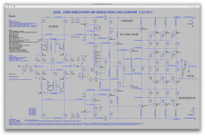
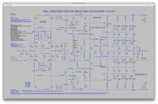
I swapped the BD139/40 vas and pre-drivers for the 2SA1381/2SC3503 (Bob's models), and cleaned up a bit for visual.
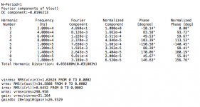
I found that oddly, lowering the bias was causing a slight drop in thd.
With about 50mA bias in each set, and the input level at 2.3V, thd is at about 0.0366% and halving the bias to about 25mA removes an other 10ppm of thd, to about 0.0356%.
It's still using the MJs from Bob's instead of the 3055s, so I don't know what the effect would be with the actual devices.
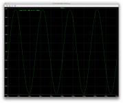
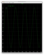
Increasing the input level a bit to get closer to maximum right before clipping causes a slight glitch on the positive side, like there was a small premature clipping with perhaps some sticking, and that of course accentuates once clipping starts actually happening.
With 2.3V input, I'm not seeing any glitch, so the thd is decent.
I ran this on a 4ohms resistive load, to be at a worst possible condition on a complex reactive 8ohms nominal load.
The Tian probe shows good stability, but I left it where it was, at the in- input. This doesn't reveal much about the inner loops.
I'll run some SOA sims to see how that looks.
I found that oddly, lowering the bias was causing a slight drop in thd.
With about 50mA bias in each set, and the input level at 2.3V, thd is at about 0.0366% and halving the bias to about 25mA removes an other 10ppm of thd, to about 0.0356%.
It's still using the MJs from Bob's instead of the 3055s, so I don't know what the effect would be with the actual devices.
Increasing the input level a bit to get closer to maximum right before clipping causes a slight glitch on the positive side, like there was a small premature clipping with perhaps some sticking, and that of course accentuates once clipping starts actually happening.
With 2.3V input, I'm not seeing any glitch, so the thd is decent.
I ran this on a 4ohms resistive load, to be at a worst possible condition on a complex reactive 8ohms nominal load.
The Tian probe shows good stability, but I left it where it was, at the in- input. This doesn't reveal much about the inner loops.
I'll run some SOA sims to see how that looks.
Attachments
I compared the intusoft model to the others I had. One of them already being from intusoft, and one was shared by Jan Didden some time ago, which looks very similar to both from intusoft.
The differences are tiny, so they are probably from the same source and perhaps have been tweaked a little.
The tweaking is likely, because most of that was a small rounding of the values, so hardly any changes, and there are a few with more significant value changes.
The most significant values that are different are IS and BF, and more modest changes for CJC, CJE, TF and TR. The one that puzzles me the most is PTF.
The intusoft model from 87 has IS at 15n, while the other one has IS at 4.66p. Jan's version has the same value as that other intusoft one.
Quite a large difference there.
The BF also has a large difference and with measurements and the datasheets, that seems much too high at 360 in the previous intusoft model, which also matches Jan's model. However, this 1987 model with BF at 75 is also somewhat off a little, as I found it should be more like 100-120 or so.
The more modest change to CJC is at 380p (intusoft 1987), compared to Jan's and the other intusoft both at 212p.
Same thing for CJE, at 520p, compared to 580p for the other 2 versions. Much less difference, but it's there.
The TF for the 87 version is cut in half compared to the others, at 40n, compared to 80n.
My early findings in tweaking the model pointed at about 60n to be closer to a typical value, which gives a Ft at a little above 2.6Mhz, which is just a little more than the 2.5Mhz typical given by most datasheets. Not for the old versions which are at 800khz usually.
And the puzzling PTF at 120, makes me wonder. Because no other models have that parameter specified at all, and the default is at 0. Only Jan's model and the other intusoft one do specify it at 120, not the 87 version.
The PTF being the excess phase. I've been trying to find out more about this, and still I don't understand it.
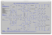
Here is the sim with a few important SOA plots.
We use the MJ models but the target is 3055, so that's the SOA against which they're plotted.
Same thing with the MJE drivers, we use the 32/33, but we don't need those beefier ones here. The 30/31 are quite sufficient, and have a little more gain.
The zip contains the whole sim. Hopefully it will run out of the box.
To view the SOA plots, just run the sim as is, and when looking at the plot, load up the SOA plot included.
We're at 2.3V input, not quite full power, and on 4 ohms resistive load.
Attachments
I have a very long to do list and took some time from it to try to help here but I have to
get back to it. I'll try to contribute more when I can.
Do you have Bob C's book or access to the how to create SPICE models section?
I believe that the original VAS in the Leach was a 1A part, that is a 100 mA part with very
little SOA at 75V nearly nothing at 150V. Consider that when it is going rail to rail with a
fast signal or especially clipping, it will go to one rail, then the opposite device has to pull
it the other way. The VAS will pull from the full rail to rail voltage and I doubt that a 100mA
part will survive. Even the 2n5401/2n5501 are 500mA parts.
These are my economical choice for all of the BD139/140 locations:
KSA1220A/KSC2690A - to126 R-O-Y 160V 1.2A 20W 19pF 150MHz 220mA @50V 90mA @100V
A bit more expensive but in a TO220 package for better cooling:
2sa1837/2sc4793 -TO220 1A 20W 220mA@50, 85mA@100V Readily available
A bit expensive:
2SC4883A/A1859A - TO220-F 20W 180V 2A 30pF 120 MHz 300mA@50V 75mA@100V
Many suggest these but their SOA is bad: 2sa1930/2sc5171
I'd probably simulate with Bob's 2N5401C and comp as close enough to any of the above parts.
Last edited:
I am definitely digging into Bob's chapter on spice models, as I go along in the process of tweaking models. It would be nice if it was that simple and straightforward, but really, it isn't. So this will take some doing. And sharing.
Just to make sure we're on the same wavelength, I'm attaching Leach's transistor selection grid that he posted on his site, which shows the few choices from the time, and I've seen many builds that were using such choices, such as the 2N3439 and 2N5416. Those are TO39 case types, which should logically be able to dissipate more than the TO92 types like the 2N5401/5551.
I haven't seen that many builds making any use of heatsinks on the TO39 parts. They must be running rather warm, but obviously not overly hot to be prone to immediate failure.
I would definitely favor TO126 case, and if a cascode was added, that would ease some more the dissipation in the vas.
The amp does have limiters for the vas (Q8/9), with the sensing resistor of 30ohms, which would place the limit somewhere near about 20mA or so, especially if using the MPSA06/56 for the limiters, with their lower Vbe, below 600mV, that should prevent the current from ever reaching anywhere near 100mA.
Regardless, using TO126 types instead of TO92 would be preferable, and they wouldn't need any heatsinking.
As long as we have decent models, we should try them, but we don't have all those exotic japanese types. At least I don't.
I thought the 2SA1381/2SC3503 would fit the bill fairly well, and not require any heatsinking.
But if we can have other models, why not compare?
I will run sims for SOA usage on the pre-drivers and vas.
Attachments

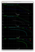
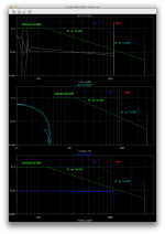
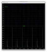
SOA plots with the 2SA1381/2SC3503 vas and pre-drivers.
On 4ohms resistive load at 20khz and 2.3V input sine.
Curious how the vas trans doesn't seem to see much Ic variation. We'll see what happens in case of clipping or shorts.
And same thing for Q14, which does see the whole voltage swing but with very little current variation, while it's quite the opposite for Q22 which sees very little voltage variation and it's not exposed to much Vce at all, while its Ic does swing quite a bit. But nothing major, well below the max and with little Vce exposition, it isn't much to dissipate and small usage of its SOA.
The green solid SOA lines are for Ta=25C, meaning no heatsinking, while the dotted cyan line shows the SOA for Tc=25C, with a very large sink to keep the case super cool (not quite practical for real).
In any case, at 4ohms resistive load and not too far from full power, we're nowhere near full SOA usage. And the 100mA level is never reached.
That's likely a different story under duress, like a short or clipping. But the limiters are there for the vas.
Attachments
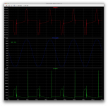
Makes me wonder: Q22 is getting very close to saturation.
I didn't look yet at closer to full power, but I'm wondering if the small glitch that I saw appearing before when getting closer to full power, wouldn't have anything to do with Q22 being at saturation...
That glitch looks rather familiar, similar to clipping with a bad behavior. It's small, but quite visible, and only appears a little before getting to full power.
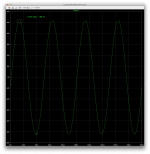
Clipping has started by 2.45V input.
The same glitch, although much smaller, also shows up at the negative side.
It grows but remains tiny though.
Clipping isn't quite symmetric, and starts at the positive side first, but not by very much. Maybe the small 3mV output offset explains it.
The same glitch, although much smaller, also shows up at the negative side.
It grows but remains tiny though.
Clipping isn't quite symmetric, and starts at the positive side first, but not by very much. Maybe the small 3mV output offset explains it.
Attachments
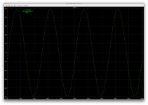
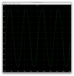
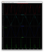
Overdriving at 2.6V input, pushes clipping a little harder (still 4ohms res ld).
Q22 is never exposed to much voltage, always less than 5V. Its Ic does go up a little on clipping, much nothing much of a threat.
The vas isn't threatened either, but the concern is more with Q14, which shows a big current spike that happens right when it has max Vce, so big time SOA violation, but for a very short time.
That spike is short, a fraction of a us, and the spike's peak is not quite reaching the pulsed max current that the device is supposed to be able to handle for short bursts. It does violate the 500us SOA by a small amount, for a tiny amount of time. Perhaps this is tolerable by the device, but what would happen in a real amp?
And I haven't looked at a short on the output yet.
This is a spike, a glitch, which may be somewhat related to Q22's saturation, maybe. But I'm just guessing there...
The clipping isn't overly ugly, it's even rather smooth at the corners, and the tiny spike looks like it's where the recovery would be, more or less. However it doesn't look really like sticking.
Attachments
I'm fairly certain that that glitch is the correct operation and it is exactly what
I was talking about previously. Device capacitances are voltage dependent and go
up in saturation, the glitch is the discharge of that capacitance to help get them
out of sticking. I would use a stronger predriver, but you could put some resistance
in series with the speed up cap that the emitter of Q14 drives.
Sticking is bad and that is why my vote is for the stronger pre driver.
If you don't see the glitch in say the diff pair, then it is not the main loop making a
correction so it must be something in the load on Q14, and that would be capacitance
or something broken in the sim. You might see a small disturbance in the diff pair
and that would be the loop trying to correct the distortion in the output caused by
that capacitance.
And, by the way, if you read Leach's write up he says that the speed up caps in that
location do not work, or do not act as (the type that he was thinking of) a speed up cap.
He was wrong, or at least thinking along a strict definition of what a speed up cap is.
If you do the analysis and find that those VAS transistors are safe, it is your choice to
use them or not. There is an old rule of thumb in power amp design to have lots of
safety margin and I am just more comfortable with a factor of 2 or 3, or more.
The EFs that drive the series stage could have their collectors go to the opposite rail
but then their dissipation would go up significantly. I don't like them getting too
close to saturation but 5V is not too bad at all.
You need to check the half voltage division of the series section which you could do
by plotting the freq response from the input to the half way series point and adjust
for reasonably flat response up to say 100 kHz.
Last edited:
I would use a stronger predriver,
Would that be just Q14/15 only?
I don't see a real need for the other set, since they never see much voltage and although they handle more current, it's still quite far from their limits.
but you could put some resistance in series with the speed up cap that the emitter of Q14 drives.
That would be C18, and I actually had tried upping its value a bit, noticing that thd went down a little bit with higher values, but I stopped at 4.7u and figured the gain in thd wasn't worth the larger cap size anyway.
The res value would be experimentally determined or calculated?
Sticking is bad and that is why my vote is for the stronger pre driver.
We could use the MJE15032/33 there from bob's lib. The 30/31 would suffice and might be better, because of their higher gain maybe, but those aren't among bob's models.
If you don't see the glitch in say the diff pair, then it is not the main loop making a correction so it must be something in the load on Q14, and that would be capacitance or something broken in the sim. You might see a small disturbance in the diff pair and that would be the loop trying to correct the distortion in the output caused by that capacitance.
There is a glitch at the ltp output. And oddly, it's the smallest there when it's the biggest at the pre-drivers.
If you do the analysis and find that those VAS transistors are safe, it is your choice to use them or not.
Well, we don't know yet what a short on the output will do. Perhaps they might be taxed some more that way than with just clipping. And that's not even taking into account whatever protections could be used. If using VI limiters, then that would definitely change things.
Usually the TO220 types have more capacitance and are less suitable for vas.
So what else to use?
The EFs that drive the series stage could have their collectors go to the opposite rail but then their dissipation would go up significantly. I don't like them getting too close to saturation but 5V is not too bad at all.
That's for Q22/23 then. Those look very safe and although I haven't looked at actual average dissipation yet, with only less than 5V max at any time, they can't be dissipating a lot.
However, almost 5V is what they will see at the max, but they do go a bit lower than 1V, which to me looks like they're pushed into saturation at the extreme end.
Since I ran that before clipping earlier (2.3V input), it may actually be even closer to full saturation at clipping. I'll look at this and post that next.
You need to check the half voltage division of the series section which you could do by plotting the freq response from the input to the half way series point and adjust for reasonably flat response up to say 100 kHz.
Not sure how to proceed with that though.
An AC analysis?
Attachments
Those SOA plots are quite nice, is there a writeup on how to do them?
I've never done them before.
There's no write up. I was going to make use of a perl script posted elsewhere in the forums, to automate this somewhat, but it wouldn't work when I tried it, and I just went back to my previous manual method.
So it's all quite manual. And somewhat time consuming, mostly when doing new devices that I haven't done before. Because I keep the data from what was already done to make new ones, which speeds things up with new sims.
Basically, the first and tedious step is extract the inflection points of the SOA curves from the datasheets' charts. Not always that easy, and those charts aren't always provided.
I'm hoping to be able to make use of a little program called Engauge, which was pointed out by our fellow diyer "de Ocampo", which can take in such charts and extract data points for the curves, which in turn can help speed things up, because the data points are one of the things where guessing can cause some errors.
Unfortunately the program didn't work, and kept crashing every time I tried it. But there's hope, as it's actively maintained and I reported the issue and the developer is working on it. Hopefully he'll be able to fix it and then I can try grabbing data points not only from SOA charts, but also from others like Vbe/Ic and the likes, to be used in models building and tweaking.
I keep a text database of the SOA curve's data points, for reuse, and also prepared code snippets using those data points for the ltspice plots. This is why subsequent work is sped up some, by not having to do the data point extractions and code writing again.
Then when I need to make up such a plot, I run the sim, grab the Ic and Vce voltages in plot panes, save the new plot with all that data, and then I go to manually edit it, using the code snippets I have prepared.
Once that's mostly ready, I look at it and do some tweaking to make it look right.
It's nothing built-in ltspice. It's all external to it. Mostly text editing.
If we switch to use other devices and models, then I will likely have to devise some more of those code snippets and prepare plots.
In the recent zipped up sim, I included the pre-made SOA plot file, and all you need to do to see it is load it up when looking at the plot.
I tweaked the latest sim by naming the important nodes, so they always keep the same name instead of being renamed every time something is changed in the schematic. This allows the plots to keep working after changes are made, otherwise they break when node names have changed.
I even played with something earlier, which was to visualize 2 SOAs from 2 similar devices, to be able to compare them at a glance. As we never see any SOA charts on top of each other, and unless we draw them up ourselves in the same chart, we can't easily compare them.
I did this to look at the SOA difference between the MJE15032/33 and the 30/31.
They are different, the 32/33 do have more SOA, mostly due to their higher voltage handling. However they do have less gain than their 30/31 brethrens.
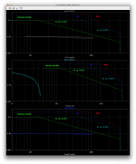
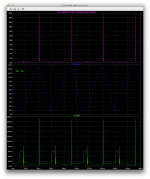
I ran the sim as earlier but again with 2.6V input, which sends it a little more into clipping. Same other conditions, 20khz, 4ohms res load.
It looks like Q22 is saturated, and it sees almost 5V at maximum of Vce.
In those conditions, the max dissipation (Q22) is only about 80mW. And average at a bit less than 45mW.
This pair isn't the one that causes much concern for SOA and dissipation. Just the saturation situation perhaps.
It looks like Q22 is saturated, and it sees almost 5V at maximum of Vce.
In those conditions, the max dissipation (Q22) is only about 80mW. And average at a bit less than 45mW.
This pair isn't the one that causes much concern for SOA and dissipation. Just the saturation situation perhaps.
Attachments
The spikes in Q14 happening at the worst Vce conditions, do bring the max dissipation at nearly 22W, but the average is about 507mW. The spike probably add a little to the average dissipation.
That's a bit much for a TO126, especially if not heatsinked, and those only handle some 7W as long as the case stays at 25C, but the 507mW average remains below its 1.2W nominal handling.
This level of overdrive isn't really something permanent and recurring, but may happen.
What other more beefy pre-driver could be used without sacrificing anything?
MJE15032/33?
Attachments
So the SOA rating plot is an overlay as I am following?
You must do the actual plot under some drive condition?
I have to think about this more, but I believe that you'd want to do it at about 39-40.5% of
full power where dissipation in the output devices is a maximum. I mention it here:
http://www.diyaudio.com/forums/soli...ells-power-amplifier-book-69.html#post2344966
Here is a bit more on my thinking about SOA:
http://www.diyaudio.com/forums/solid-state/49255-safe-operating-area-3.html#post556887
- Status
- This old topic is closed. If you want to reopen this topic, contact a moderator using the "Report Post" button.
- Home
- Amplifiers
- Solid State
- Super Leach amp simulation woes