Unfortunate that this requires boosted rails for the front end:
http://www.diyaudio.com/forums/soli...100-mkii-single-ended-folded-cascode-vas.html
The Leach followed Otala's formula of high diff pair degeneration, and wide open loop gain -
VAS degeneration. This leads to lower loop gain available for overall distortion reduction.
I already made the VAS more Self Blameless like through the addition of the .5uf cap.
You could lower the diff pair degeneration making it very close to a Blameless concept,
and/or as we've said try different compensation schemes, Miller inclusive or TMC. I've not
tried TMC in practice and not heard from anyone if there are any issues.
I think that the oscillations that people saw in the Leach was local due to wiring inductance,
since you are planning all one PC it should help keep wiring inductance to a minimum.
I don't have a strong preference for an alternate topology. I'm planning to do something
with JFETs in the front end soon, but only to try something different.
People seem to like the Slewmaster but I've not take a close look at the schematics. His
designs are usually based on other favorites - nothing wrong with that.
Unfortunate that this requires boosted rails for the front end:
http://www.diyaudio.com/forums/soli...100-mkii-single-ended-folded-cascode-vas.html
Well this is more complicated for the psu, but not too much of a show stopper. If it really helps, why not?
The Leach followed Otala's formula of high diff pair degeneration, and wide open loop gain -
VAS degeneration. This leads to lower loop gain available for overall distortion reduction.
Yes, and I remember working on a few amps back in the late 70s that were designed with Otala's concept in mind. They were fully symmetrical, which I liked, and they all had degen and local feedbacks all over the place, reducing the open loop gain.
I more recently did a few sims on those old designs, and they all have that same thing in common, as with the leach designs, the thd is high. So the goal of reducing tim lead to much increased thd. Exchanging one type of distortion for an other. It seems tim is much harsher on the ears than hd is, and I guess that's why the high thd doesn't seem to disturb many people, who find the leach low tim better to listen to.
I think with the newer designs, both reduced tim and low thd can be achieved and without resorting to too much degen and reduced open loop gain.
An amp with fast enough slew rate and just enough degen to avoid input saturation should be able to avoid the apparition of tim, even if the open loop gain is much higher.
I already made the VAS more Self Blameless like through the addition of the .5uf cap. You could lower the diff pair degeneration making it very close to a Blameless concept,
Why not! I see nothing wrong with Self's blameless concept, and it shouldn't leave too much opening for tim to occur.
and/or as we've said try different compensation schemes, Miller inclusive or TMC. I've not tried TMC in practice and not heard from anyone if there are any issues.
I tried that on this superamp, but at the time I didn't remove the inner feedback loop, and going tmc didn't bring real improvements.
I'm wary of touching that inner loop, with too little understanding of it. So short of removing it altogether, I just don't touch it.
Lately I tried tmc also on our latest design, and it was about the same as regular comp, so perhaps the inner loop is also preventing the full effect.
I think that the oscillations that people saw in the Leach was local due to wiring inductance, since you are planning all one PC it should help keep wiring inductance to a minimum.
That's probably what was happening, especially since most of those builds were done using the old methods with wires going to power devices and the likes. Too much long wiring and connections, that can bring more troubles.
And that's also why I don't like the diodes for the thermal comp. I would change that, even if it takes using diodes with cases that can bolt on a sink.
No SMT, and no wires.
I don't have a strong preference for an alternate topology. I'm planning to do something with JFETs in the front end soon, but only to try something different.
I always favor fully symmetric topo, and I never liked any kind of fets in the signal path. Just a personal preference. So no mosfet amps for me.
I might consider fets in the current sources for example, but I'm not hot on using fets for other things.
People seem to like the Slewmaster but I've not take a close look at the schematics. His designs are usually based on other favorites - nothing wrong with that.
Nope, nothing at all. It works quite nicely.
Ok, now I remember looking into this before, and saved the forum pages. I will have to re-read all that. But I don't remember finding a full blown solution that satisfied me.
You might be surprised with the distortion if you drop the diff pair degen to 0 or 10 ohms,
100 ohms might be a good compromise.
What I like about fully complementary designs is having a dual VAS so that the output
stage is driven in both directions. Single VAS is only driven by whatever the current
source is set to, on that side. But there are a several things that I do not like:
NPN and PNP Comps are not really comp.
Having to not only match same type but opposite types - duals are nice.
BJTs finite base current
A single diff pair has outputs with both polarities (most do not use both polarities) and
has the advantage that if you can find a dual (JFETs or BJTs) then no matching is required.
I think the best is single diff pair with one of the "flippers" to take the other polarity output
and drive the opposite side VAS. See Fig 7.14 in Bob's book but watch out for the error.
Many have noted this in the APT-1 amp, some Harman Kardons. Ostripper has looked at a
lot of amps, he says this is from a Luxman that is similar to the APT-1 that was 2011 not sure
of his favorite these days:
http://www.diyaudio.com/forums/soli...lls-power-amplifier-book-206.html#post2624749
I'm planning to try something like that or a folded cascode if that works out better.
Last edited:
Oscillation issues with Super pair, Hawksford Cascode, etc.:
http://www.diyaudio.com/forums/solid-state/25172-baxandall-super-pair.html
http://www.diyaudio.com/forums/solid-state/166306-origins-baxandall-super-pair.html
http://www.diyaudio.com/forums/solid-state/25172-baxandall-super-pair.html
http://www.diyaudio.com/forums/solid-state/166306-origins-baxandall-super-pair.html
As much as I don't like comp diff very much I am building one myself just to see what can
be done with the old KSA-50 topology.
This design by Valery might be of interest if you want a modernized comp diff. I've not dug
too deep into it but it looks very clean and you can discuss local stability issues with others
building his design if any crop up:
http://www.diyaudio.com/forums/soli...-old-ideas-1970s-ips-ops-186.html#post5038808
You might be surprised with the distortion if you drop the diff pair degen to 0 or 10 ohms, 100 ohms might be a good compromise.
Not so surprising, with a bit more open loop gain.
I dropped the base res to 100ohms along with the degen ones, then adjusted the compensation to keep enough margins.
The thd at 20k is cut in more than half, just below 0.02%, and at first, before adjusting the compensation, it was down to just below 0.0184%, but there was only about 22deg of phase margin, so not enough, and I adjusted this.
I couldn't get the margins as high as with 300ohms, but still about 60deg/24db, so not too bad.
I adjusted the value of the big cap on the feedback, to drop the thd at the low end to decent values compared to the rest of the spectrum. With 2200u there is no increase of thd at 20hz in regards to higher frequencies, so it's not so huge a value, with a low voltage cap like 6V3 or so, those aren't so big, and we can add diodes in parallel with it to protect it.
I ran stepped frequency sims and here's what we get:
.step freq=20
Total Harmonic Distortion: 0.002998%(0.000000%)
.step freq=50
Total Harmonic Distortion: 0.003018%(0.000000%)
.step freq=1000
Total Harmonic Distortion: 0.003270%(0.000000%)
.step freq=5000
Total Harmonic Distortion: 0.005883%(0.000000%)
.step freq=10000
Total Harmonic Distortion: 0.010580%(0.002547%)
.step freq=20000
Total Harmonic Distortion: 0.019972%(0.017832%)
thd is climbing fast beyond 1khz, but we're maxing out near 0.02% by 20khz, so not so bad.
I would be tempted to do this compared to the 300ohms version.
The drop from 300 to 100ohms degen gives about 10db more of open loop gain.
The lower base res values also reduces noise.
This is at 4ohms resistive load. Simulating for worst case 8ohms complex load.
Attachments
A modern Leach with less degeneration, and MIC compensation:
http://www.diyaudio.com/forums/solid-state/306159-ati-amplifier-schematic.html#post5040817
Interesting diode protection that you might want to try.
http://www.diyaudio.com/forums/solid-state/306159-ati-amplifier-schematic.html#post5040817
Interesting diode protection that you might want to try.
Thinking a bit more, I seem to remember you saying that you could use slow or fast outputs
and perhaps just change some compensation.
BUT, there never were PNP devices made in the slow single diffused technology and
therefore it is not possible to build this amp with the very slow devices. I do not
recommend using the very slow devices anyway.
and perhaps just change some compensation.
BUT, there never were PNP devices made in the slow single diffused technology and
therefore it is not possible to build this amp with the very slow devices. I do not
recommend using the very slow devices anyway.
This Onkyo employs a front end that outlines how I'd do a single ended diff pair
driving a push pull VAS, very nice. I might not do the biasing exactly the same but
something similar:
http://www.diyaudio.com/forums/soli...r-complementary-output-stage.html#post5050126
driving a push pull VAS, very nice. I might not do the biasing exactly the same but
something similar:
http://www.diyaudio.com/forums/soli...r-complementary-output-stage.html#post5050126
I notice the feed-forward loop is different on Ver. 1 compared to Ver 2.1a for the Double Barrelled Amp.
Takeoff was on the O/P of the 1/2V dividing triple and Dr. Leach moved it to the O/P of the first transistor of that triple. I think he was trying to avoid some delay with the last two/triple, at the expense of less FB coverage in that inner loop. I don't know the margins here with the fT 2MHz (MJ15003/4) O/P transistors. Would be nice to compare.
spookydd, what are you using for S/W in your sims?
I've been sick for the past couple of weeks and am just now getting somewhat better. Trying to emerge and get back to business...
I looked this over and besides the 3EF output, I'm not seeing it much as a leach. The front end isn't even cascoded and it uses current sources, so nothing really in common there besides the fact that it's symmetric ltp.
There is no inner loop from the predrivers either. But that C2 cap???
And those HF loads on each ltp output, I've seen this on bryston amps.
Those back to back diodes on the ltp inputs, with the amount of degen present, may be more a cause for clipping the fast input transients. I've simulated ltp stages with varying degen values to see how much headroom is gained, and unless there is no degen at all or a very small amount of it, the diodes can only get in the way instead of doing any good.
Those diodes can be useful with no degen, as they can prevent overloading on the ltp. Once the degen gets a little heavier, there is far more than enough headroom and it takes a lot more to overload that ltp, so then diodes there are just forcing an early clipping.
Among those test sims for ltp degen, I tried varying the base stoppers, and didn't find them to make much difference. What are they really good for then? If they're just acting as plain base stoppers, they don't need to have a high value.
One other odd thing is that bias spreader with 3 trannies, instead of the diodes based leach spreader. Is it really necessary to have such an arrangement? Wouldn't a single tran spreader be sufficient?
I must say I don't quite understand how this thing really works, and what is the role of those 3 diode strings.
For one thing, that type of protection can't be soa, and it doesn't act on the drive signal. The way I see it, this schematic is incomplete when it comes to protections, and something is left off that pertains to what it actually acts on.
I'm suspecting some type of clamp or crowbar or something of that nature. That "PRO" output looks like an all on option...
Plus that Q126 thingy looks like it must be trying to DC detect, sort of...
A modern Leach with less degeneration, and MIC compensation:
http://www.diyaudio.com/forums/solid-state/306159-ati-amplifier-schematic.html#post5040817
I looked this over and besides the 3EF output, I'm not seeing it much as a leach. The front end isn't even cascoded and it uses current sources, so nothing really in common there besides the fact that it's symmetric ltp.
There is no inner loop from the predrivers either. But that C2 cap???
And those HF loads on each ltp output, I've seen this on bryston amps.
Those back to back diodes on the ltp inputs, with the amount of degen present, may be more a cause for clipping the fast input transients. I've simulated ltp stages with varying degen values to see how much headroom is gained, and unless there is no degen at all or a very small amount of it, the diodes can only get in the way instead of doing any good.
Those diodes can be useful with no degen, as they can prevent overloading on the ltp. Once the degen gets a little heavier, there is far more than enough headroom and it takes a lot more to overload that ltp, so then diodes there are just forcing an early clipping.
Among those test sims for ltp degen, I tried varying the base stoppers, and didn't find them to make much difference. What are they really good for then? If they're just acting as plain base stoppers, they don't need to have a high value.
One other odd thing is that bias spreader with 3 trannies, instead of the diodes based leach spreader. Is it really necessary to have such an arrangement? Wouldn't a single tran spreader be sufficient?
Interesting diode protection that you might want to try.
I must say I don't quite understand how this thing really works, and what is the role of those 3 diode strings.
For one thing, that type of protection can't be soa, and it doesn't act on the drive signal. The way I see it, this schematic is incomplete when it comes to protections, and something is left off that pertains to what it actually acts on.
I'm suspecting some type of clamp or crowbar or something of that nature. That "PRO" output looks like an all on option...
Plus that Q126 thingy looks like it must be trying to DC detect, sort of...
Thinking a bit more, I seem to remember you saying that you could use slow or fast outputs
and perhaps just change some compensation.
BUT, there never were PNP devices made in the slow single diffused technology and
therefore it is not possible to build this amp with the very slow devices. I do not
recommend using the very slow devices anyway.
I have doubts that I do have any of the slowest original devices. I do have an old amp that I was using back then in the 70s, which was a quasi, all 3055s, and perhaps those may be the older types, but not sure.
The older parts would have a much lower Vce0, and so far, all I've tested have shown the much higher Vce0 than stated on the old devices' datasheets, so if they have the much higher Vce0, they must also be the newer faster devices.
I have a few of the BDX18 types that were among the first true complementary possibilities back then, and although some old datasheets are stating Ft at 800khz, some don't state anything, and the others are stating 4Mhz typical, so I suspect the BDX18 were just like the MJ2955 and perhaps even the 2N2955, made with newer methods and faster with higher Vce0.
I don't think we have to bother worrying about any function with the oldest devices.
I notice the feed-forward loop is different on Ver. 1 compared to Ver 2.1a for the Double Barrelled Amp.
Takeoff was on the O/P of the 1/2V dividing triple and Dr. Leach moved it to the O/P of the first transistor of that triple.
Do you have a schematic to post for comparison?
I'm only looking at the latest version, and the inner loop looks the same on the regular and super leach, with the pickup being made on the predrivers.
spookydd, what are you using for S/W in your sims?
What do you mean?
I looked this over and besides the 3EF output, I'm not seeing it much as a leach. The front end isn't even cascoded and it uses current sources, so nothing really in common there besides the fact that it's symmetric ltp.
I view the diff pair cascode on the Leach being their mainly to allow the use of lower voltage
devices, yes it is also a cascode. Comp diff, VAS with no beta multiplier, triple output are
what say Leach to me, dont care where the diff pair tail current comes from.
All the other differences, MIC etc. might be good to consider.
The back to back diodes are to protect the amp from massive overload of the input, 10V or
something like that.
I did not look closely, but the diode strings are probably like the protection diodes on the
JE990 which was a common method for very simple output protection, right not SOA.
Hope you feel 100% better soon.
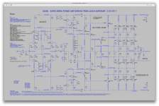
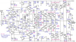
Schematic for original Double Barrelled amp
Here is my schematic for Ver. 1 (as I call it) of the Double Barrelled amp, from the original Audio Magazine 1980 article. Added mark ups for component value differences with Ver. 2.1a
I note the feed-forward takeoff is different, and like early Low-TIM's, main NFB is only to the output (no HF NFB from the driver).
I built this amp in the 80's and decided I need to retire it and build a new one.
Researching Dr. Leach's updates and mods to use fT 30MHz O/P transistors... This is why I am interested in your sims. I can't afford to troubleshoot oscillating triples, lol.
Are you using LTSpice for example?
Attachments
Last edited:
This is very interesting protection, OP reports that relay contacts welded closed
response was to use .01 ohm RDS power FETs on power rails that open on fault:
http://www.diyaudio.com/forums/solid-state/191449-output-relays-3.html#post2619002
Relays are tricky.
response was to use .01 ohm RDS power FETs on power rails that open on fault:
http://www.diyaudio.com/forums/solid-state/191449-output-relays-3.html#post2619002
Relays are tricky.
- Status
- This old topic is closed. If you want to reopen this topic, contact a moderator using the "Report Post" button.
- Home
- Amplifiers
- Solid State
- Super Leach amp simulation woes