6N6P ~ ECC99 ~ 12BH7
Thank you muchly.
")
Wait Gm of 6N6P is 11,200uMhos and 12BH7 is 3100uMhos???
Last edited:
Please always do a search before you ask for the models:
http://www.diyaudio.com/forums/tube...-post4161385.html?highlight=ecl86#post4161385
http://www.diyaudio.com/forums/tube...-post4161385.html?highlight=ecl86#post4161385
Hi - I've been looking all over (yes, used the search) for 50EH5 models (or its equivalent with other heater voltages - 6EH5, 12EH5) and no luck. I'd be willing to figure out how to do it based on the sheets, if I could find a place that listed the LSpice value definitions. Anyone come across the 50EH5 model and can point the way for me, please? Thanks!
If you are a bit skilled in MS Excel you can scan a V-I chart, convert to a CSV file, set up the equations and use MS-Solver to set a "minima".
It's really beautiful if you set the options under "solve" to watch the program iterate, but also important to remember that these are only approximations.
It's really beautiful if you set the options under "solve" to watch the program iterate, but also important to remember that these are only approximations.
You can also try Model Paint Tool. In this case, use paint_kip.jar for tracing the pentode.
You can also try Model Paint Tool. In this case, use paint_kip.jar for tracing the pentode.
Yes, the Excel method works well but can give results which don't always agree with the physics!
As a side-bar, Nutonian Eurequa is no longer available as freeware.
Wow, thanks, awesome suggestions! I'll try Model Paint Tool first and see how that goes. Frank's Tube Data Sheets ( https://frank.pocnet.net/sheets5.html ) has five different 50EH5 data sheets with graphs to choose from, so one of them should do the trick. I'll keep you posted.
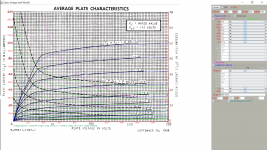
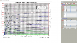
Well, I tried the Model Paint Tool I'm not sure if it'll work on the 50EH5. If you look at any of the Plate Voltage / current graphs on the 50EH5, the curves jump up fast then bend horizontal. If the object of the program is to adjust the sliders to make red lines match the ones on the graph, I'm at a loss how to get it to do that. The examples shown all have the same generally forward then up-sloping curves that the initial "red lined graph" pops up with. Ah well.
See if you can improve over mine:
**** 50EH5 ******************************************
* Created on 03/25/2017 13:50 using paint_kip.jar
* Model Paint Tools: Trace Tube Parameters over Plate Curves, Interactively
* Plate Curves image file: 50eh5.png
* Data source link: <plate curves URL>
*----------------------------------------------------------------------------------
.SUBCKT PENT_50EH5 1 2 3 4 ; P G K G2
+ PARAMS: CCG=17P CGP=0.65P CCP=9P RGI=2000
+ MU=160 KG1=58 KP=97.9 KVB=14.8 KVC=2.11 VCT=2.35 EX=0.574 KG2=54.1
* Vp_MAX=200 Ip_MAX=140 Vg_step=1 Vg_start=0 Vg_count=9
* Rp=1600 Vg_ac=23.5 P_max=5 Vg_qui=-23.4 Vp_qui=240 UL=0.43 EG2=115
* X_MIN=96 Y_MIN=52 X_SIZE=1114 Y_SIZE=788 FSZ_X=1799 FSZ_Y=967 XYGrid=true
* showLoadLine=n showIp=y isDHP=n isPP=n isAsymPP=n isUL=n showDissipLimit=y
* showIg1=n gridLevel2=n isInputSnapped=n
* XYProjections=n harmonicPlot=y harmonics=y
*----------------------------------------------------------------------------------
RE1 7 0 1G ; DUMMY SO NODE 7 HAS 2 CONNECTIONS
E1 7 0 VALUE= ; E1 BREAKS UP LONG EQUATION FOR G1.
+{V(4,3)/KP*LOG(1+EXP((1/MU+(VCT+V(2,3))/V(4,3))*KP))}
G1 1 3 VALUE={(PWR(V(7),EX)+PWRS(V(7),EX))/KG1*ATAN(V(1,3)/KVB)}
* Alexander Gurskii screen current, see audioXpress 2/2011
RE2 8 3 1G ; Dummy
G2 8 3 VALUE={(PWR(V(7),EX)+PWRS(V(7),EX))/KG2*(KVC-ATAN(V(1,3)/KVB))}
E2 8 4 VALUE={0} ; Dummy
RCP 1 3 1G ; FOR CONVERGENCE
C1 2 3 {CCG} ; CATHODE-GRID 1
C2 1 2 {CGP} ; GRID 1-PLATE
C3 1 3 {CCP} ; CATHODE-PLATE
R1 2 5 {RGI} ; FOR GRID CURRENT
D3 5 3 DX ; FOR GRID CURRENT
.MODEL DX D(IS=1N RS=1 CJO=10PF TT=1N)
.ENDS
*$
Edit: Screen current should be using the current scale on the right, or 1/2 scale on the left, so need adjustment. I try to adjust KG2 to 137.4 the screen current is halved.
Attachments
Last edited:
See if you can improve over mine:
<snip>
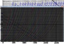
It's close. the lower -V lines aren't quite there, but I tweaked it a bit to bring the 0V line up to about 100ma at 150V, which is where it is on the datasheet graphs, and the upper lines are pretty close. The lower ones seem to not curve up and over like the upper ones, though. Not sure what to do about that.
The lower ones seem to not curve up and over like the upper ones, though. Not sure what to do about that.
Where it matters is where you will use it, not at the extremes.
304TL is four 75TL. You can find the spice model for 75TL, then multiplied the whole equation below by four(?). At Va 1kV, Vg 0, Ia is 250mA for 75TL, and 1A for 304TL.Does anybody have a 304TL or 304TH LT Spice model ?
https://gist.github.com/chanmix51/6947361#file-tetrodes_pentodes-sub
https://www.audioasylum.com/cgi/t.mpl?f=tubediy&m=122944
Here is 75TL spice model:
* 75TL LTSpice model
.subckt 75TL P G K
Bp P K I=((0.008071931767m)+(3.503608694e-005m)*V(G,K))*uramp((11.35872332)*V(G,K)+V(P,K)+(-21.07038254))**1.5 * V(P,K)/(V(P,K)+(-4.024455933))
*Multiplied the above by 4 for 304TL
.ends 75TL
Attachments
Last edited:
**** 304TL Composite DHT *****************************************
* Created on 03/26/2017 23:01 using paint_kit.jar 3.0
* Model Paint Tools: Trace Tube Parameters over Plate Curves, Interactively
* Plate Curves image file: 304tl.jpg
* Data source link:
*----------------------------------------------------------------------------------
.SUBCKT 304TL 1 2 3 4 ; P G K1 K2
+ PARAMS: CCG=12.1P CGP=8.6P CCP=0.8P RFIL=10
+ MU=12 KG1=15206.4 KP=52.9 KVB=24192 VCT=21.8 EX=1.9 RGI=2000
* Vp_MAX=2800 Ip_MAX=500 Vg_step=10 Vg_start=20 Vg_count=22
* Rp=4000 Vg_ac=55 P_max=300 Vg_qui=-48 Vp_qui=300
* X_MIN=91 Y_MIN=201 X_SIZE=1409 Y_SIZE=765 FSZ_X=1942 FSZ_Y=1102 XYGrid=true
* showLoadLine=n showIp=y isDHT=y isPP=n isAsymPP=n showDissipLimit=y
* showIg1=n gridLevel2=n isInputSnapped=n
* XYProjections=n harmonicPlot=n harmonics=y
*----------------------------------------------------------------------------------
RFIL_LEFT 3 31 {RFIL/4}
RFIL_RIGHT 4 41 {RFIL/4}
RFIL_MIDDLE1 31 34 {RFIL/4}
RFIL_MIDDLE2 34 41 {RFIL/4}
E11 32 0 VALUE={V(1,31)/KP*LOG(1+EXP(KP*(1/MU+V(2,31)/SQRT(KVB+V(1,31)*V(1,31)))))}
E12 42 0 VALUE={V(1,41)/KP*LOG(1+EXP(KP*(1/MU+V(2,41)/SQRT(KVB+V(1,41)*V(1,41)))))}
RE11 32 0 1G
RE12 42 0 1G
G11 1 31 VALUE={(PWR(V(32),EX)+PWRS(V(32),EX))/(2*KG1)}
G12 1 41 VALUE={(PWR(V(42),EX)+PWRS(V(42),EX))/(2*KG1)}
RCP1 1 34 1G
C1 2 34 {CCG} ; CATHODE-GRID
C2 2 1 {CGP} ; GRID=PLATE
C3 1 34 {CCP} ; CATHODE-PLATE
D3 5 3 DX ; FOR GRID CURRENT
D4 6 4 DX ; FOR GRID CURRENT
RG1 2 5 {2*RGI} ; FOR GRID CURRENT
RG2 2 6 {2*RGI} ; FOR GRID CURRENT
.MODEL DX D(IS=1N RS=1 CJO=10PF TT=1N)
.ENDS
*$
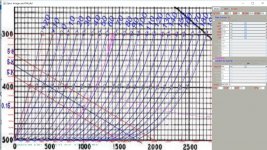
This model is based on transpose of 304TL constant current datasheet found on this page.
* Created on 03/26/2017 23:01 using paint_kit.jar 3.0
* Model Paint Tools: Trace Tube Parameters over Plate Curves, Interactively
* Plate Curves image file: 304tl.jpg
* Data source link:
*----------------------------------------------------------------------------------
.SUBCKT 304TL 1 2 3 4 ; P G K1 K2
+ PARAMS: CCG=12.1P CGP=8.6P CCP=0.8P RFIL=10
+ MU=12 KG1=15206.4 KP=52.9 KVB=24192 VCT=21.8 EX=1.9 RGI=2000
* Vp_MAX=2800 Ip_MAX=500 Vg_step=10 Vg_start=20 Vg_count=22
* Rp=4000 Vg_ac=55 P_max=300 Vg_qui=-48 Vp_qui=300
* X_MIN=91 Y_MIN=201 X_SIZE=1409 Y_SIZE=765 FSZ_X=1942 FSZ_Y=1102 XYGrid=true
* showLoadLine=n showIp=y isDHT=y isPP=n isAsymPP=n showDissipLimit=y
* showIg1=n gridLevel2=n isInputSnapped=n
* XYProjections=n harmonicPlot=n harmonics=y
*----------------------------------------------------------------------------------
RFIL_LEFT 3 31 {RFIL/4}
RFIL_RIGHT 4 41 {RFIL/4}
RFIL_MIDDLE1 31 34 {RFIL/4}
RFIL_MIDDLE2 34 41 {RFIL/4}
E11 32 0 VALUE={V(1,31)/KP*LOG(1+EXP(KP*(1/MU+V(2,31)/SQRT(KVB+V(1,31)*V(1,31)))))}
E12 42 0 VALUE={V(1,41)/KP*LOG(1+EXP(KP*(1/MU+V(2,41)/SQRT(KVB+V(1,41)*V(1,41)))))}
RE11 32 0 1G
RE12 42 0 1G
G11 1 31 VALUE={(PWR(V(32),EX)+PWRS(V(32),EX))/(2*KG1)}
G12 1 41 VALUE={(PWR(V(42),EX)+PWRS(V(42),EX))/(2*KG1)}
RCP1 1 34 1G
C1 2 34 {CCG} ; CATHODE-GRID
C2 2 1 {CGP} ; GRID=PLATE
C3 1 34 {CCP} ; CATHODE-PLATE
D3 5 3 DX ; FOR GRID CURRENT
D4 6 4 DX ; FOR GRID CURRENT
RG1 2 5 {2*RGI} ; FOR GRID CURRENT
RG2 2 6 {2*RGI} ; FOR GRID CURRENT
.MODEL DX D(IS=1N RS=1 CJO=10PF TT=1N)
.ENDS
*$
This model is based on transpose of 304TL constant current datasheet found on this page.
Attachments
Last edited:
Wow! thats good work indeed! Thank you so much!!
However, please keep in mind that the GM of 75TL is 3350 so 4X 3350=13400 while the GM of 304TL is 16700 which is like having 5X 75TLs in parallel.
Thankyou veeeeery much for all your excellent work!
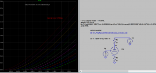
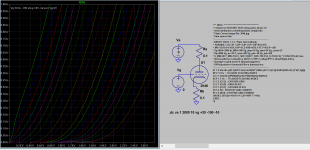
I just don't get consistence model generated by the paint tool with different data entries, and the one I posted is inaccurate, so here is another model generated that I found is closer. So please verify by plotting it out before you use it.
I try to generate even more accurate model if I can later. The paint tool seems to be a little buggy for now, could be due to the Java in my OS.
**** 304TL Composite DHT *****************************************
* Created on 03/27/2017 16:02 using paint_kit.jar 3.0
* Model Paint Tools: Trace Tube Parameters over Plate Curves, Interactively
* Plate Curves image file: 304tl.jpg
* Data source link:
*----------------------------------------------------------------------------------
.SUBCKT 304TL 1 2 3 4 ; P G K1 K2
+ PARAMS: CCG=12.1P CGP=8.6P CCP=0.8P RFIL=10
+ MU=12 KG1=915 KP=72 KVB=31488 VCT=0.231 EX=1.36 RGI=2060
* Vp_MAX=2800 Ip_MAX=500 Vg_step=10 Vg_start=20 Vg_count=22
* Rp=4000 Vg_ac=55 P_max=300 Vg_qui=-48 Vp_qui=300
* X_MIN=71 Y_MIN=162 X_SIZE=1409 Y_SIZE=761 FSZ_X=1934 FSZ_Y=1094 XYGrid=true
* showLoadLine=n showIp=y isDHT=y isPP=n isAsymPP=n showDissipLimit=y
* showIg1=y gridLevel2=n isInputSnapped=n
* XYProjections=n harmonicPlot=n harmonics=y
*----------------------------------------------------------------------------------
RFIL_LEFT 3 31 {RFIL/4}
RFIL_RIGHT 4 41 {RFIL/4}
RFIL_MIDDLE1 31 34 {RFIL/4}
RFIL_MIDDLE2 34 41 {RFIL/4}
E11 32 0 VALUE={V(1,31)/KP*LOG(1+EXP(KP*(1/MU+V(2,31)/SQRT(KVB+V(1,31)*V(1,31)))))}
E12 42 0 VALUE={V(1,41)/KP*LOG(1+EXP(KP*(1/MU+V(2,41)/SQRT(KVB+V(1,41)*V(1,41)))))}
RE11 32 0 1G
RE12 42 0 1G
G11 1 31 VALUE={(PWR(V(32),EX)+PWRS(V(32),EX))/(2*KG1)}
G12 1 41 VALUE={(PWR(V(42),EX)+PWRS(V(42),EX))/(2*KG1)}
RCP1 1 34 1G
C1 2 34 {CCG} ; CATHODE-GRID
C2 2 1 {CGP} ; GRID=PLATE
C3 1 34 {CCP} ; CATHODE-PLATE
D3 5 3 DX ; FOR GRID CURRENT
D4 6 4 DX ; FOR GRID CURRENT
RG1 2 5 {2*RGI} ; FOR GRID CURRENT
RG2 2 6 {2*RGI} ; FOR GRID CURRENT
.MODEL DX D(IS=1N RS=1 CJO=10PF TT=1N)
.ENDS
*$
I settled for just triode model, it generated more accurate model than DHT, hope you like it, and if you know why DHT model is less accurate, let us know.
**** 304TL ******************************************
* Created on 03/27/2017 20:35 using paint_kit.jar 3.0
* Model Paint Tools: Trace Tube Parameters over Plate Curves, Interactively
* Plate Curves image file: 304tl.jpg
* Data source link:
*----------------------------------------------------------------------------------
.SUBCKT 304TL 1 2 3 ; Plate Grid Cathode
+ PARAMS: CCG=12.1P CGP=8.6P CCP=0.8P RGI=270
+ MU=12 KG1=11921.5 KP=57.2 KVB=9575.1 VCT=18 EX=1.88
* Vp_MAX=2800 Ip_MAX=500 Vg_step=10 Vg_start=20 Vg_count=22
* Rp=4000 Vg_ac=55 P_max=300 Vg_qui=-48 Vp_qui=300
* X_MIN=88 Y_MIN=192 X_SIZE=1408 Y_SIZE=758 FSZ_X=1934 FSZ_Y=1094 XYGrid=true
* showLoadLine=n showIp=y isDHT=n isPP=n isAsymPP=n showDissipLimit=y
* showIg1=n gridLevel2=n isInputSnapped=n
* XYProjections=n harmonicPlot=n harmonics=y
*----------------------------------------------------------------------------------
E1 7 0 VALUE={V(1,3)/KP*LOG(1+EXP(KP*(1/MU+(VCT+V(2,3))/SQRT(KVB+V(1,3)*V(1,3)))))}
RE1 7 0 1G ; TO AVOID FLOATING NODES
G1 1 3 VALUE={(PWR(V(7),EX)+PWRS(V(7),EX))/KG1}
RCP 1 3 1G ; TO AVOID FLOATING NODES
C1 2 3 {CCG} ; CATHODE-GRID
C2 2 1 {CGP} ; GRID=PLATE
C3 1 3 {CCP} ; CATHODE-PLATE
D3 5 3 DX ; POSITIVE GRID CURRENT
R1 2 5 {RGI} ; POSITIVE GRID CURRENT
.MODEL DX D(IS=1N RS=1 CJO=10PF TT=1N)
.ENDS
*$
Attachments
- Home
- Amplifiers
- Tubes / Valves
- Vacuum Tube SPICE Models