Your tapped horn design has a throat chamber - where is the equivalent to that in your BP6 design?
Post #7157 details the changes necessary to make the acoustic paths of the two systems, and therefore the results, equivalent.
All that is the Sd x the .75 inch thickness of wood. The feature is grayed out in BP6. If the throat chamber is zeroed out in TH, I'm quite sure the TH graph will not look like the BP6 graph.
All that is the Sd x the .75 inch thickness of wood. The feature is grayed out in BP6.
I gather from your comment that you have not attempted to include an equivalent to the tapped horn throat chamber in your BP6 design, so for the purposes of the comparison exercise, I will remove the throat chamber from the tapped horn design.
The tapped horn design now has three lumped-element acoustical components:
1. Segment 1
2. Segment 2
3. Segment 3
The BP6 design has four lumped-element acoustical components:
1. Chamber 1
2. Chamber 2
3. Port 1
4. Port 2
How do chambers 1 and 2 and ports 1 and 2 in your BP6 design relate to segments 1, 2 and 3 in the modified tapped horn design? In other words, what numbers should replace the four question marks in the table below?
BP6 chamber 1 = TH segment ?
BP6 chamber 2 = TH segment ?
BP6 port 1 = TH segment ?
BP6 port 2 = TH segment ?
The requested information will help me to better understand the design assumptions you are making.
Since the TH has a straight flare, I split the volume of TH segment 2 in half.
TH S1 + (TH S2 / 2) volumes = BP6 C1.
TH S3 + (TH S2 / 2) volumes = BP6 C2.
TH S1 area = BP6 P1 and P2 areas.
0.75 inch of wood = BP6 P1 and P2 lengths.
Since the TH has a straight flare, I split the volume of TH segment 2 in half.
TH S1 + (TH S2 / 2) volumes = BP6 C1.
TH S3 + (TH S2 / 2) volumes = BP6 C2.
TH S1 area = BP6 P1 and P2 areas.
0.75 inch of wood = BP6 P1 and P2 lengths.
Should
(TH S2 or S3 × L23)/2 = BP6 C1
(TH S2 or S3 × L23)/2 = BP6 C2
TH S1 = BP6 P1 area
TH S4 = BP6 P2 area
TH L12 = BP6 P1 length
TH L34 = BP6 P2 length?
Now you have really confused me.
Maybe this will help to clarify things...
Look at the schematic diagrams for the two loudspeakers. In the case of the BP6 system, the volume velocity from the left side of the driver diaphragm "flows" though chamber 1 and then through port tube 1. In the case of the tapped horn, the volume velocity from the throat side of the driver diaphragm divides into two, with one component "flowing" back into closed segment 1, and the other component "flowing" forward into segment 2. The acoustic paths through the two loudspeaker systems are clearly not the same, hence a difference in the results.
I see your point.
BP6 chamber 1 = TH segment 1 & 2 volumes.
BP6 chamber 2 = TH segment 3 volume.
BP6 port 1 & 2 diameter = TH S1 or TH S4 (straight flare).
BP6 port 1 & 2 length = 0.75 inch (1.905 cm) thickness of wood
Thank you David!
Hello dear David! Here's what I got. Final version. What do you think?
Hi Cubana,
Everything looks fine to me, but the ultimate decision has to be yours
") .
.Kind regards,
David
Hi BP1Fanatic,
I knew that we would get there eventually.
Another simple sanity check...
Looking at the two schematic diagrams once again, the port tube 2 outlet is the only point where sound radiates from the BP6 system, and the segment 3 mouth is the only point where sound radiates from the TH system. This means that BP6 port tube 2 has to be the equivalent of TH segment 3, or part thereof.
Kind regards,
David
I see your point.
I knew that we would get there eventually
.BP6 chamber 1 = TH segment 1 & 2 volumes.
BP6 chamber 2 = TH segment 3 volume.
BP6 port 1 & 2 diameter = TH S1 or TH S4 (straight flare).
BP6 port 1 & 2 length = 0.75 inch (1.905 cm) thickness of wood
Another simple sanity check...
Looking at the two schematic diagrams once again, the port tube 2 outlet is the only point where sound radiates from the BP6 system, and the segment 3 mouth is the only point where sound radiates from the TH system. This means that BP6 port tube 2 has to be the equivalent of TH segment 3, or part thereof.
Kind regards,
David
Hello David, Hello every brother, I am new member. I am from Thailand. Brother advised me. thank you brother.
Hi Piyapong38,
Welcome to the Hornresp thread!
Kind regards,
David
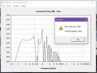
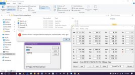
I received this error when I click on Filter Wizard.
Hi BP1Fanatic,
Everything works fine for me.
I suspect that your filter data has been corrupted - perhaps it is related to the problem reported in Post #7122.
http://www.diyaudio.com/forums/subwoofers/119854-hornresp-713.html#post5008733
Could you please post a copy of the exported record file as an attachment, so that I can check.
Thanks,
David
Another simple sanity check...
Looking at the two schematic diagrams once again, the port tube 2 outlet is the only point where sound radiates from the BP6 system, and the segment 3 mouth is the only point where sound radiates from the TH system. This means that BP6 port tube 2 has to be the equivalent of TH segment 3, or part thereof.
Kind regards,
David
Actually, I was able to keep both ports at the 1.905cm length when creating the BP6 in Nd mode. The response looks similar to the TH graph. However, I still can't get the BP6 mode to spit out a similar graph with the same enclosure volume. When I get back on my laptop, I'll post the pics. I'm also going to try CH mode too.
Hi BP1Fanatic,
Could you please post a copy of the exported record file as an attachment, so that I can check.
Thanks,
David
I will when I get back home tonight.
Thanks for all of your help David!
Hi BP1Fanatic,
Could you please post a copy of the exported record file as an attachment, so that I can check.
Thanks,
David
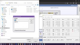
I'm missing the Export folder in HR! I'm going to reinstall HR.
Attachments

- Home
- Loudspeakers
- Subwoofers
- Hornresp