In the case of a back loaded horn the 150 hertz lowpass is a good thing.
Hi Mark,
Thanks for clarifying this point. On re-reading my Post #7136 I can see that my 'out of context' comments on the effect of throat chamber size would have confused things nicely, particularly when we are talking about back-loaded horns. That will teach me to post messages in a hurry - lesson learned!
") .
.Kind regards,
David
Hi Mark,
Thanks for clarifying this point. On re-reading my Post #7136 I can see that my 'out of context' comments on the effect of throat chamber size would have confused things nicely, particularly when we are talking about back-loaded horns. That will teach me to post messages in a hurry - lesson learned!
Kind regards,
David
All water under the bridge Master McBean.
I'm probably the most guilty of making posts that express half of what I was thinking. It's a sign of a busy person. Fixing the post is a sign of a busy person who cares.
Currently trying to understand the acoustic loading of sealed vs. ported back-volumes for a horn. Checking Hornresp for the acoustic loading in my 'bodge' of reducing the front horn to only 1cm , looks like I'm only seeing the analysis of the loading of the horn bit (!) ie. not the box. Electrically, I see the peaks and how they change with back-volume & porting though. Is there a way to check the acoustic loading of the back volume or alternatively - put the ported box on the front where the horn would normally be ( or use 'combined response' to somehow check this ? ) .
Is there a way to check the acoustic loading of the back volume
Hi IslandPink,
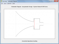
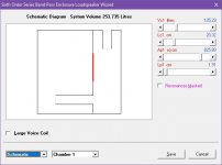
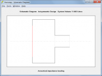
Use the compound horn (CH) arrangement shown in the attachments.
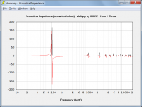
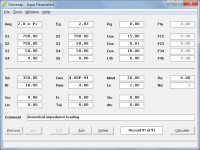
The acoustical impedance loading the "ported box side" of the diaphragm is given by Attachment 3.
Kind regards,
David
Attachments
Could you talk me through the locations of S along the box+tube and along the horn?
How does the software know that S4 is at the end of the tube and that S5 is the start of a new volume?
Does Lrc, Vrc define the box volume between the driver's cone and the throat of the horn?
along the box+tube and along the horn?How does the software know that S4 is at the end of the tube and that S5 is the start of a new volume?
Does Lrc, Vrc define the box volume between the driver's cone and the throat of the horn?
Hey David,
How come this enclosure does not model the same as a BP6 and a straight flare tapped horn?
How come this enclosure does not model the same as a BP6 and a straight flare tapped horn?
Attachments
Hi AndrewT,
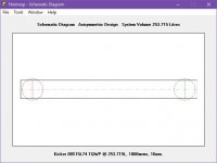
Referring to the schematic diagram:
S1 = cross-sectional area of the box at the diaphragm
S2 = cross-sectional area of the box at the port
S3 = cross-sectional area of the port tube inlet
S4 = cross-sectional area of the port tube outlet
S5 = cross-sectional area of the horn throat
S6 = cross-sectional area of the horn mouth
(If L56 is changed from Exp to Con or Par, the Loudspeaker Wizard can then be used and the area sliders altered while looking at the schematic diagram to check the area locations).
Because a compound horn (CH) system has been specified.
In the case of a compound horn system, yes.
Kind regards,
David
Could you talk me through the locations of S
Referring to the schematic diagram:
S1 = cross-sectional area of the box at the diaphragm
S2 = cross-sectional area of the box at the port
S3 = cross-sectional area of the port tube inlet
S4 = cross-sectional area of the port tube outlet
S5 = cross-sectional area of the horn throat
S6 = cross-sectional area of the horn mouth
(If L56 is changed from Exp to Con or Par, the Loudspeaker Wizard can then be used and the area sliders altered while looking at the schematic diagram to check the area locations).
How does the software know that S4 is at the end of the tube and that S5 is the start of a new volume?
Because a compound horn (CH) system has been specified.
Does Lrc, Vrc define the box volume between the driver's cone and the throat of the horn?
In the case of a compound horn system, yes.
Kind regards,
David
How come this enclosure does not model the same as a BP6 and a straight flare tapped horn?
Hi BP1Fanatic,
I have not checked that your two examples are physically identical, but assuming that they are, the results will still be different for the following reasons:
In the case of the BP6 arrangement, the port tubes have end corrections added where appropriate, and a parallel topology is used. In the case of the TH arrangement, there are no end corrections, and a series topology is used. The models have been individually optimised based on assumptions made as to how they would normally be used. Your examples would appear to have "stretched the envelope" a little
.The BP6 model could of course be changed to make the results the same as for the TH model simply by removing the end corrections and assuming a serial topology. I would rather not do this though, as traditionally, the conventional BP6 model has end corrections, and uses a parallel topology.
End corrections and a parallel topology would not make much sense for a conventional tapped horn.
Kind regards,
David
Thanks for the info, David. Some interesting options to play with there !
Hi IslandPink,
Just to clarify - it is not necessary to use the CH option if only the acoustical impedance is required. The attached simpler arrangement will give the same result.
Kind regards,
David
Attachments
Inductance Calculation
@ David McBean
I think it should be possible for HR to Auto calculate voice coil inductance
At the moment we can input this ourselves, from data sheets. But as with the T/S specs, HR & other simmmers, can more precicely calculate specs by cross referencing them as we input certain ones in a certain order.
I discovered this formula today from here http://www.sbacoustics.com/index.php/download_file/-/view/191
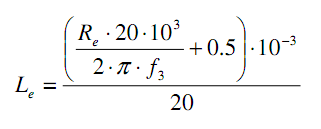
Could this, or something similar/better, be incorporated into HR ?
@ David McBean
I think it should be possible for HR to Auto calculate voice coil inductance
At the moment we can input this ourselves, from data sheets. But as with the T/S specs, HR & other simmmers, can more precicely calculate specs by cross referencing them as we input certain ones in a certain order.
I discovered this formula today from here http://www.sbacoustics.com/index.php/download_file/-/view/191
Could this, or something similar/better, be incorporated into HR ?
Attachments

I have not checked that your two examples are physically identical
I have now had time to check.
The TH and BP6 systems are not equivalent. It is like comparing apples and oranges.
It is not surprising that the results should be different
.
Could this, or something similar/better, be incorporated into HR ?
Hi Zero D,
The quoted empirical formula requires a value for f3 - which in turn is dependent upon the value of Le, which we don't know and are trying to calculate
.f3 = frequency at which the electrical impedance is 3dB above Zmin
I think that the formula is probably intended to be used where the driver impedance has actually been measured, and you want to get a rough idea of the driver voice coil inductance based on that measurement.
In our case, we would first need a value for Le so that we could produce an electrical impedance chart to find f3, which would then allow us to calculate Le using the given formula (we need to know Le in the first place though, to be able to calculate the chart, which defeats the purpose of the formula). Out of interest, I worked through the exercise using the Hornresp default driver mounted in an infinite baffle with Re = 6 ohms and Le = 1 millihenry, resulting in a f3 value of 1389 Hz. The calculated value of Le using the quoted formula then becomes 0.71 mH (compared to the actual input value used of 1.00 mH).
Kind regards,
David
The attached simpler arrangement will give the same result.
David
Thanks - will try that too. Certainly a ported box seems to give some very interesting results on paper - esp with regard to phase on the 'combined' output. I'm certain though it will be a case of building and listening to understand it properly.
@ David McBean
Thanx for looking into this Interesting that Le drops to 0.71 when done like that ! I tried it on a IB too, & sealed & ported, & even though it does affects the fr, it doesn't appear to make a huge difference, with that particular default driver anyway !
Maybe with higher initial Le drivers, it might make a bigger difference, i havn't tried it yet. But, they usually are big powerful bass drivers, so the f drop at the higher end of the range, shouldn't be a concern.
Sorry to have kept you up later than usual
Thanx for looking into this
Interesting that Le drops to 0.71 when done like that ! I tried it on a IB too, & sealed & ported, & even though it does affects the fr, it doesn't appear to make a huge difference, with that particular default driver anyway ! Maybe with higher initial Le drivers, it might make a bigger difference, i havn't tried it yet. But, they usually are big powerful bass drivers, so the f drop at the higher end of the range, shouldn't be a concern.
Sorry to have kept you up later than usual
The TH and BP6 systems are not equivalent. It is like comparing apples and oranges.
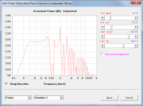
Comparing apples with apples…
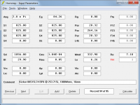
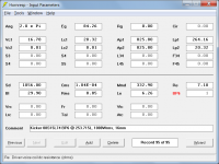
If the throat chamber is removed from the given tapped horn example, a BP6 system can then be specified that is equivalent to the tapped horn, and produces identical results because the cross-sectional areas of the port tubes in the BP6 system are relatively large, meaning that end corrections are not added in the simulation model.
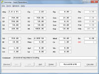
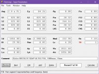
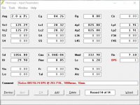
Attachment 1 shows the input parameter values for the given tapped horn example without the throat chamber.
Attachment 2 shows the input parameter values for a BP6 system equivalent to the tapped horn shown in attachment 1.
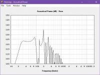
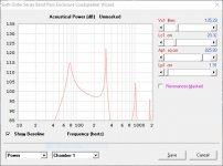
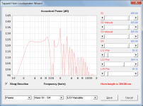
Attachment 3 shows the power response for the tapped horn shown in attachment 1.
Attachment 4 shows the power response for the BP6 system shown in attachment 2.
Attachments
Sorry to have kept you up later than usual
Not a problem (says he, yawning...)
.I have now had time to check.
The TH and BP6 systems are not equivalent. It is like comparing apples and oranges.
It is not surprising that the results should be different
What exactly is not equivalent? I know the volumes are different by.02 liters. That should not make a huge difference in response.
What exactly is not equivalent?
Your tapped horn design has a throat chamber - where is the equivalent to that in your BP6 design?
Post #7157 details the changes necessary to make the acoustic paths of the two systems, and therefore the results, equivalent.
- Home
- Loudspeakers
- Subwoofers
- Hornresp