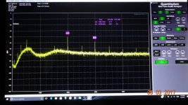
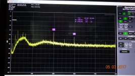
ARTA 44100Hz, 131072 points, RBW 336.5mHz, BW 22kHz.
The beef question is how the ARTA is presenting the data! This means if a max/peak detector algorithm is used (as the default on most FFT SW), than your result is may not as good as you expected.
May change the FFT size to check how this deals ..
Hp
I don't think we should use just singular method to take these measurements. Several methods should be used and all should reasonable agree.
The mass of the electron wasn't determined using a single test. If it were it would likely be wrong.
When I did the measurement with passive Twin T I stepped the gain up in 10dB steps. I had to give the TT 90dB of gain before the harmonics stood out well enough to measure.
As far as the Shibasoku 725D is concerned the only difference is the notch filters were bypassed. Every test I done on the 725D and 725C show no large amplitude error.
What is happening with noise when active notch filter using positive feedback is used?
What happens with the noise such that the FFT can't resolve the noise properly?
Does it matter if the noise is not white?
I disagree that an active notch filter will cause any more inaccuracy than a passive notch. Does it add distortion and noise? Absolutely. Can this obscure the harmonics of the DUT? Absolutely. But it not less accurate.
The beef question is how the ARTA is presenting the data! This means if a max/peak detector algorithm is used (as the default on most FFT SW), than your result is may not as good as you expected.
May change the FFT size to check how this deals ..
Hp
ARTA does have a peak hold function. This set manually by user and is listed in with the AVG selections. Most software I've used the default is 'None'.
My original question was relative to a claim of <-150dB on all harmonics, if -+10dB answers are OK that's important to know. Dave's plot looks very reasonable.
Doesnt matter, Scott. Its been a wild goose chase but confirmed the ultra low numbers. My data is much closer to David's. One thing you might take note of... we are not measuring the same generator. As I had told, I readjusted the internal controls of my generator for slightly better thd on my 725D. There are noted differences in Harmonic levels (2H/3H). But still very close and ultra low.
It is great generator... and specifically, I asked to have a continuously variable frequency, rather than spot frequencies. David took the suggestion/challenge and made it tunable and still super low THD. And, sweepable.
Congrates to him ! Two thumbs up. I hope he can commercialize it or sell design and make some money for his effort.... while having a full time job and family. I can recognize talent when i see it.

THx-Richard
Last edited:
Doesnt matter, Scott. Its been a wild goose chase but confirmed the ultra low numbers. My data is much closer to David's. One thing you might take note of... we are not measuring the same generator. As I had told, I readjusted the internal controls of my generator for slightly better thd on my 725D. There are noted differences in Harmonic levels (2H/3H). But still very close and ultra low.
It is great generator... and specifically, I asked to have a continuously variable frequency, rather than spot frequencies. David took the suggestion/challenge and made it tunable and still super low THD. And, sweepable.
Congrates to him ! Two thumbs up. I hope he can commercialize it or sell design and make some money for his effort.... while having a full time job and family. I can recognize talent when i see it.
THx-Richard
The kid moved out finally. That leaves the wife and job.
This means if a max/peak detector algorithm is used (as the default on most FFT SW), than your result is may not as good as you expected.
Never heard of such a thing, I have never seen anything but the magnitude of the complex result of the DFT as default without a large warning, with noise this would be less than useless.
Once again about the FFT variables and the averaging. Here are some pictures.
Input signal was the noise mixed with the 2500Hz tone at -80dB level.
FFT length 16384, zero averaging (the signal is hardly seemed):
http://content32-foto.inbox.lv/albums/e/elterra/FFTvaria/FFTL0.jpg
FFT length 16384, 10 averages:
http://content32-foto.inbox.lv/albums/e/elterra/FFTvaria/FFTL10.jpg
FFT length 524288, zero averaging:
http://content32-foto.inbox.lv/albums/e/elterra/FFTvaria/FFTH0.jpg
FFT length 524288, 10 averages:
http://content32-foto.inbox.lv/albums/e/elterra/FFTvaria/FFTH10.jpg
Probably display can't properly show the noise floor, when the data massive is very big, but the signal level has no seemed error.
Victor.
A few years ago Samuel Groner shared a paper on new windowing functions for FFT.
Some of them forced the FFT to display the noise at -200dB.
I posted that paper here too. I think if you check the idea was to get the skirts on the FFT's down to below -200dB or more close to the tones, the equivalent noise BW was actually degraded as a result. The examples were numerical at double precision so the noise floor was ~-300dB. Windowing always increases the equivalent noise BW of the bins (see Dick's AP app note from a couple of days ago). Only flat no weighting leaves it at 1.
As far as the Shibasoku 725D is concerned the only difference is the notch filters were bypassed. Every test I done on the 725D and 725C show no large amplitude error.
What is happening with noise when active notch filter using positive feedback is used?
What happens with the noise such that the FFT can't resolve the noise properly?
I don't have a Shibasoku anymore but I'm sure you are testing the limits of what can be done. There is value in knowing the results can be repeated independently.
Today, with some extra patience and more fine tuning of controls, I found a few more dB improvements --- 4dB lower harmonics.
My final results for David's generator design...... 2H = -145dB and 3H = -154dB
I surrender, you've beaten me into submission flux capacitors and all.
David,
It is worthwhile to increase the power supply filtering cap on the A5 board/ It got rid of most ac line related harmonis showing up on the monitor output.
These are C112, 113. Increased from 47 to 470mfd/25vdc/105c
the monitor signal comes out of A5/ U17. an NEC C813c 8 pin dip IC. What is it? I used to know.
THx-Richard
David,
the monitor signal comes out of A5/ U17. an NEC C813c 8 pin dip IC. What is it? I used to know.
THx-Richard
Its just an opamp. Might see if a less noisy jFET substitute helps lower noise on monitor output.
-RNM
David,
It is worthwhile to increase the power supply filtering cap on the A5 board/ It got rid of most ac line related harmonis showing up on the monitor output.
These are C112, 113. Increased from 47 to 470mfd/25vdc/105c
the monitor signal comes out of A5/ U17. an NEC C813c 8 pin dip IC. What is it? I used to know.
THx-Richard
Supper beta matched bipolar input transistor low noise op amp. According to the data sheet.
Never heard of such a thing, I have never seen anything but the magnitude of the complex result of the DFT as default without a large warning, with noise this would be less than useless.
May read some R&S stuff on selecting Detector's
http://cdn.rohde-schwarz.com/pws/dl_downloads/dl_common_library/dl_manuals/gb_1/e/espi_1/ESPI_Operating_Manual_en_FW442.pdf
The question here is not averaging multiple FFT spectrum's! The real beef comes how like a 64k FFT level/Bin data array is reduced to a 1K display array (what is visible on screen)!
For pure noise measurement: None FFT Window have to be used and the detector (data reduce mode) mode should be AVERAGE !
Hp
Supper beta matched bipolar input transistor low noise op amp. According to the data sheet.
25nV/sqrt/Hz.... not too low noise. I'll change it and see.
-RNM
Last edited:
25nV/sqrt/Hz.... not too low noise. I'll change it and see.
-RNM
If it has 100dB gain, referred to the input of the analyzer, behind it I don't think 25nV/rtHz will add to much to that.
One way to beat all the noise is to lock the oscillator to the sampling clock and stop using FFT tools that require power of 2 time records and that give you complete access to the complex FFT data. For instance 1kHz at 96kHz is in exactly bin 1000, the seconds in bin 2000, etc. Now vector average the results rather than power average. All popular sampling frequencies have small prime factors so the FFT takes little or no speed hit. You can't tell the execution time difference between 100 65536 vs 96000 FFT's for instance.
- Home
- Design & Build
- Equipment & Tools
- Low-distortion Audio-range Oscillator

