This is a well known and well documented issue . Here is how HP dealt with it before digital meters were easily implemented: http://www.hpl.hp.com/hpjournal/pdfs/IssuePDFs/1961-03.pdf And Sensitive Research had a system to manually mark every indication on thir meters. Still accuracy below 1/3 of full scale was diminished. Also if you add the noise to the readings the lower part of the scale is not so accurate on low level measurements. Log scale meters (with linear dB steps) were better because the zero was suppressed.
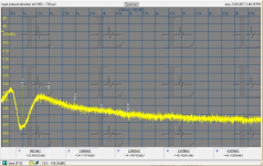
This plot is about the best I can get from the 725 at this stage. This is a 262144 point FFT and a 192 KHz sample rate with Victor's oscillator on battery power. I need to figure out how to improve the input amp.
This plot is about the best I can get from the 725 at this stage. This is a 262144 point FFT and a 192 KHz sample rate with Victor's oscillator on battery power. I need to figure out how to improve the input amp.
Attachments
Jan,
I think we all understand this about meter accuracy. There is nothing to prevent the accuracy of a meter being corrected in hardware, firmware. In the all analog days, meter scales were or at least some had custom printed scales based on individual meter error. we did this often for our custom designs. Noise of this instrument is lower than stock and well below the .1 on the scale. On this instrument, it is accurate to -130dbv or to the -20 marking. Below that is not spec'ed. But I am using it to show the noise and distortion is something less than -130dBv. In any event, we have to go to the monitor output for accurate measure below -130dbv
lets not loose sight of that. No measurement data claims were made based upon the meter reading below -130 - - no matter how accurate the meter reading is at the low end of the scale. The FFT via monitor output is what we are using for levels below -130. In fact, this very low meter reading is the reason we have to use the monitor output and run it thru FFT processing.
To SW's comment... I am using 2v and not one volt. 6dB.
The 6dB was corrected for in FFT software of the QA401, as shown.
THx-Richard
Last edited:
This is a well known and well documented issue . Here is how HP dealt with it before digital meters were easily implemented: http://www.hpl.hp.com/hpjournal/pdfs/IssuePDFs/1961-03.pdf And Sensitive Research had a system to manually mark every indication on thir meters. Still accuracy below 1/3 of full scale was diminished. Also if you add the noise to the readings the lower part of the scale is not so accurate on low level measurements. Log scale meters (with linear dB steps) were better because the zero was suppressed.
This plot is about the best I can get from the 725 at this stage. This is a 262144 point FFT and a 192 KHz sample rate with Victor's oscillator on battery power. I need to figure out how to improve the input amp.
Looks more believable, BTW as Waly said I remain disappointed that the noise averaging re:FFT's remains so misunderstood. You CAN NOT reduce the noise by averaging no matter how many averages you do, you can only reduce the bin to bin variance the mean remains the same (the noise BW of the bins always matters). Synchronous averaging of the noise in preference to the harmonics would require two matched Shibasoku's, and a lot more (see, for instance, the NIST battery noise paper posted here numerous times).
Last edited:
Looks more believable, BTW as Waly said I remain disappointed that the noise averaging re:FFT's remains so misunderstood. You CAN NOT reduce the noise by averaging no matter how many averages you do, you can only reduce the bin to bin variance the mean remains the same (the noise BW of the bins always matters). Synchronous averaging of the noise in preference to the harmonics would require two matched Shibasoku's, and a lot more (see, for instance, the NIST battery noise paper posted here numerous times).
"Synchronous averaging of the noise in preference to the harmonics would require two matched Shibasoku's"
And why would this be a requirement?
What does the meter accuracy have to do with the FFT plots Richard has been posting here?
"Consider the FFT software process. The noise is highly averaged. The FFT bandwidth is far far less than the noise BW of the oscillator."
Where is this statement does it say that averaging lowers the noise floor?
I think there was an assumption made here. I have no confusion about averaging.
Last edited:
Looks more believable, BTW as Waly said I remain disappointed that the noise averaging re:FFT's remains so misunderstood. You CAN NOT reduce the noise by averaging no matter how many averages you do, you can only reduce the bin to bin variance the mean remains the same (the noise BW of the bins always matters). Synchronous averaging of the noise in preference to the harmonics would require two matched Shibasoku's, and a lot more (see, for instance, the NIST battery noise paper posted here numerous times).
Amen to this!
OT, check this old Brit stuff, the dancing chick is Mr. Lydon's step daughter, unfortunately she passed away few years ago. He lived very close to my parents house, Ariane was a friend of my mother (and so was her mentor Joe Strummer of Clash fame), then she moved abroad with her hubby, in the early 80s.
https://youtu.be/ZyXGblps64M
"Synchronous averaging of the noise in preference to the harmonics would require two matched Shibasoku's"
And why would this be a requirement?
What does the meter accuracy have to do with the FFT plots Richard has been posting here?
"Consider the FFT software process. The noise is highly averaged. The FFT bandwidth is far far less than the noise BW of the oscillator."
Where is this statement does it say that averaging lowers the noise floor?
I think there was an assumption made here. I have no confusion about averaging.
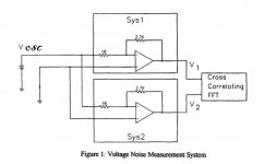
Here Sys1 and Sys2 would be two identical systems for removing the fundamental frequency.
http://www.mikrocontroller.net/attachment/100819/Measurement_of_Chemical_Battery_noise.pdf
EDIT - You added a comment, I apologize if I misinterpreted this but your comment here makes no sense to me (noise BW of oscillator?). The fact remains Dick's plot remains unbelievable by 15-20dB, a 5nV noise floor would require ~1.4kOhm total real part of source impedance in the entire notch filter and amplifier chain the Shibasiku can not synchronously average the noise.
Consider the FFT software process. The noise is highly averaged. The FFT bandwidth is far far less than the noise BW of the oscillator
Attachments
Last edited:
Amen to this!
OT, check this old Brit stuff, the dancing chick is Mr. Lydon's step daughter, unfortunately she passed away few years ago. He lived very close to my parents house, Ariane was a friend of my mother (and so was her mentor Joe Strummer of Clash fame), then she moved abroad with her hubby, in the early 80s.
https://youtu.be/ZyXGblps64M
A Friday night regular on the TT circa 1980, too bad about Ari Up. I'm partial to "Earth Beat" too.
Here Sys1 and Sys2 would be two identical systems for removing the fundamental frequency.
http://www.mikrocontroller.net/attachment/100819/Measurement_of_Chemical_Battery_noise.pdf
EDIT - You added a comment, I apologize if I misinterpreted this but your comment here makes no sense to me (noise BW of oscillator?). The fact remains Dick's plot remains unbelievable by 15-20dB, a 5nV noise floor would require ~1.4kOhm total real part of source impedance in the entire notch filter and amplifier chain the Shibasiku can not synchronously average the noise.
Sorry Scott if I made no sense. Reading it again myself it makes no sense.
You must understand at the end of the work day I don't have much left in me and I'm not always clear. I'm working outside all day in -25 deg C, roughly 18 deg F. It sucks the life out of me.
Last edited:
Here Sys1 and Sys2 would be two identical systems for removing the fundamental frequency.
http://www.mikrocontroller.net/attachment/100819/Measurement_of_Chemical_Battery_noise.pdf
EDIT - You added a comment, I apologize if I misinterpreted this but your comment here makes no sense to me (noise BW of oscillator?). The fact remains Dick's plot remains unbelievable by 15-20dB, a 5nV noise floor would require ~1.4kOhm total real part of source impedance in the entire notch filter and amplifier chain the Shibasiku can not synchronously average the noise.
Maybe I misunderstand Shibasoku's noise reduction DSP. I'll post what Shibasoku says about it and let you decide what it is.
Demian has described the process as synchronous averaging as well.
By the way I have never made any claims about the distortion of my oscillator. I have only posted measurements and explained how I got them.
I questioned the scale of one of your measurements a few years back based on the noise floor. because it was lower than what the EMU can do. You had added gain and re scaled ARTA to agree with the measurement. This caused the noise floor to appear lower than what it really was.
We should get to the bottom of why there is a noise floor discrepancy in Richards FFT measurement.
The 2nd harmonic in the plot Demain posted is only 5 dB higher. The various models of 725 can very that much.
Sorry Scott if I made no sense. Reading it again myself it makes no sense.
You must understand at the end of the work day I don't have much left in me and I'm not always clear. I'm working outside all day in -25 deg C, roughly -18 deg F. It sucks the life out of me.
No problem, just trying to keep the answers sensible.
I may have caused some confusion. What the 725 does is synchronous sampling of the signal and reconstructs the harmonics from the samples. By averaging the harmonics are sable and the noise component between the harmonics doesn't exist in the measurements. Synchronous averaging would do the same but you need a stable source that you are synchronizing to.
The input amp on the 725 uses a differential Jfet pair as followers to a bipolar pair. I think the best case input noise would be around 4-5 nV/rtHz. The jfets are cascoded references to their sources to minimize the input capacitance and change in capacitance with voltage. However the gain is from the bipolar pair. In effect they are all adding input noise so its really not going to get better. if you go down range the gain of the stage increases but the noise is constant. Going up rage (10V+) the input attenuator limits the noise floor. For a 100 K input there are no easy ways to improve it.
Its quite possible for the oscillator to have less noise but not easy to confirm. Adding a passive notch between the oscillator and a low noise amp would need a notch with low effective impedance, which may well induce more distortion.
One confusor may be the output scaled against 1V (meter full scale) and the input which is best at around 3V. There are a lot of moving parts to manage and getting the scaling off is way too easy. I also sometimes find distortion at levels higher in the FFT than the distortion analysis shows. Its something I need to sort out.
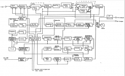
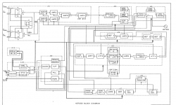
Scott here are some bits from Shibasoku on the 725 and the noise reduction system.
Two block diagrams of the 725B and 725C.
A page from the manual giving the noise reduction formula.
Shibasoku's patent of their noise reduction system.
The formula in from the manual looks like a moving average to me.
The sampler is phase locked to the fundamental. There is a counter in the PLL loop to multiply the PLL output. The PLL output generates the sample pulses. With the fundamental suppressed by the notch filters, the remaining fundamental and it's harmonics are synchronously sampled. If the harmonics are relatively constant there average is a constant. If the noise is random it is continuously averaged down.
That's my take on it.
https://www.google.com/patents/US4417310
Attachments
I may have caused some confusion. What the 725 does is synchronous sampling of the signal and reconstructs the harmonics from the samples. By averaging the harmonics are sable and the noise component between the harmonics doesn't exist in the measurements. Synchronous averaging would do the same but you need a stable source that you are synchronizing to.
The input amp on the 725 uses a differential Jfet pair as followers to a bipolar pair. I think the best case input noise would be around 4-5 nV/rtHz. The jfets are cascoded references to their sources to minimize the input capacitance and change in capacitance with voltage. However the gain is from the bipolar pair. In effect they are all adding input noise so its really not going to get better. if you go down range the gain of the stage increases but the noise is constant. Going up rage (10V+) the input attenuator limits the noise floor. For a 100 K input there are no easy ways to improve it.
Its quite possible for the oscillator to have less noise but not easy to confirm. Adding a passive notch between the oscillator and a low noise amp would need a notch with low effective impedance, which may well induce more distortion.
One confusor may be the output scaled against 1V (meter full scale) and the input which is best at around 3V. There are a lot of moving parts to manage and getting the scaling off is way too easy. I also sometimes find distortion at levels higher in the FFT than the distortion analysis shows. Its something I need to sort out.
Right. It's an error in the naming of the Shibasoku process. Similar to synchronous averaging by affect but not quite the same.
I think the same mistake is made in vibration analysis where I've seen synchronous sampling referred to as synchronous averaging.
I think i said here that i put in 1 volt and meter on front panel is 1.0 v (one volt range) and full scale is full scale at monitor output also... also 1 v. And with added tone at -60dBv it comes out on monitor as expected.
David is correct. Of course noise of the instrument isnt lowered with FFT.... There is no measuring instrument which indicates there is a large error. I have used several SOTA brands all with similar results with same generator or others to compare. Only 2 instruments are used...... either 725D and QA401. I'll recheck software cal for 401. Also recompare with AP2722A again. But david has similar gear and get similar results.
David's gen is extreamly good compared to other ultra low distortion gens. Maybe we need further clarification of what the large error might be due to.....? Would love to find something no one else has yet.
THx-Richard
Last edited:
Right. It's an error in the naming of the Shibasoku process. Similar to synchronous averaging by affect but not quite the same.
It's more a sort of lock-in amplifier. Noise is statistically independent time point to time point so there is no self reference as with a sine wave. Another point, the depth of the noise in the notch around the fundamental (if it can be resolved) would be where you see the instruments front end noise. This would assume the skirts on the oscillator are low enough this close to the fundamental.
The Shibasoku noise reduction system is used in analysis mode. THD mode is another name for it.
Richard is not measuring in this mode in the plot posted. The analyzer is in normal mode.
THD+N. In this mode the 725 functions the same as any THD+N distortion analyzer.
The only processing is from the QA401.
Later today I'll repeat the measurement here with my SVO and a QA400. See where the noise floor is at. I don't trust what the FFT displays the noise at.
The Shibasoku noise reduction system is used in analysis mode. THD mode is another name for it.
Yes in the analysis mode the amplitude of the harmonics is the only information, it's like an FFT where the resolution is set by the fundamental frequency i.e. the bins are at fo, 2Xfo, 3Xfo, etc. This is from when FFT systems were rare and/or expensive. With an FFT you only need the spurs to be 10db > than the noise level to be within 1dB accuracy, at 20dB for 0.1dB accuracy.
I ordered a couple of Victor's oscillators, as Bruce Hofer showed me 30yr ago a passive notch is unambiguous and with care can approach the -140/150 THD level and at single frequencies the easiest way to verify performance.
If Richard's plot is normal mode from the block diagram IMO there is an error in computing the reference level.
Last edited:
Richard's plot does show a lower noise floor than my plots. But he is doing this with a QA401 where I'm using the EMU0204. This shouldn't matter if everything is calibrated. But it is home and garden stuff. Not intended to be a used as precision instrument.
The QA stuff is for sure not a calibrated path.
Dick Moore observed some weirdness with the sound cards and ARTA near the bottom of the scale. He referred to it as a gain compression (error).
The QA stuff is for sure not a calibrated path.
Dick Moore observed some weirdness with the sound cards and ARTA near the bottom of the scale. He referred to it as a gain compression (error).
- Home
- Design & Build
- Equipment & Tools
- Low-distortion Audio-range Oscillator