The C3503/A1381 models you are using saturate very early. I don't get the problem when I switch them to Cordell's models.
The sim as I zipped it was having those pointing to the BD139/140, which are from his library. Although I had not changed the parts names in the schematic, I did have them point somewhere else, with ako. Same thing with the power devices, as I've been trying out various models.
If you can get this sim to work properly all the way, I'd like to see that, and with which models.
I think it would be an interesting build for 2N3055/MJ2955.
I just realized the models files in the zip duplicate the MPSA parts.
The 2SA/2SC and the BD models are from cordell's library.
The KSA/KSC are from fairchild, but I haven't used those yet.
So even though the sim has those 2SA/2SC parts pointing at the BD models, they're actually all from cordell's library, including the BCs from the input stage.
The 2SA/2SC and the BD models are from cordell's library.
The KSA/KSC are from fairchild, but I haven't used those yet.
So even though the sim has those 2SA/2SC parts pointing at the BD models, they're actually all from cordell's library, including the BCs from the input stage.
Trying to read up on early effect and voltage. I'm realizing something and need to make sure I get that right.
As I understand it, the larger the early voltage, the flatter the Ic/Vbe curve is (lower and less inclined).
Is that how it is?
And having looked (with a spice test rig) at an overly simplified model missing a lot of parameters (including VAF and VAR), I must conclude that when that parameter is missing, spice assumes an infinite value for those and the curves end up totally horizontal.
Early on we settled on using a value of 150 for the 2N3055, and I assume this is for VAF and not VAR.
I think the default value for Vaf if it's not specified is 100. I may be wrong. If you look at the Q section of Elements in the LTSpice manual, it will list all the default values. This is preferred because it allows a person to quickly do some experiments with the blank NPN and PNP models and get reasonable results.
Ic/Vbe very closely follows an exponential function, Vaf only shifts Vbe. Transconductance is still mainly determined by current, regardless of Vce. Transistors held at a constant current by the bias scheme, which is the norm, will have their Ib or Hfe affected, and the slight Vbe change will often be inconsequential.
I prefer to think about Vaf this way: it is the voltage at which Hfe doubles. So if at 1V Hfe is 300 and Vaf is 40, Hfe will be about 600 at 40V. This illustrates something that not many here don't seem to notice - low Hfe transistors with low Early voltage can actually have pretty high Hfe at higher voltages, although the extra Early effect often taints the benefits of this.
Cordell has models for the BC5x0 transistors, the 3503/1831 and the MJLxxxxx which we know are not greatly flawed. Getting models from unknown sources usually gives you a grab bag with some ridiculous crap mixed in. Often it is better to substitute missing models for the few hand-made models that are known good, because finding the "right" model in historical model libraries tends to give you something totally different than what you wanted. I've seen models which were just copies of other models with parameter changes that looked made-up.
As I understand it, the larger the early voltage, the flatter the Ic/Vbe curve is (lower and less inclined).
Is that how it is?
Ic/Vbe very closely follows an exponential function, Vaf only shifts Vbe. Transconductance is still mainly determined by current, regardless of Vce. Transistors held at a constant current by the bias scheme, which is the norm, will have their Ib or Hfe affected, and the slight Vbe change will often be inconsequential.
I prefer to think about Vaf this way: it is the voltage at which Hfe doubles. So if at 1V Hfe is 300 and Vaf is 40, Hfe will be about 600 at 40V. This illustrates something that not many here don't seem to notice - low Hfe transistors with low Early voltage can actually have pretty high Hfe at higher voltages, although the extra Early effect often taints the benefits of this.
Cordell has models for the BC5x0 transistors, the 3503/1831 and the MJLxxxxx which we know are not greatly flawed. Getting models from unknown sources usually gives you a grab bag with some ridiculous crap mixed in. Often it is better to substitute missing models for the few hand-made models that are known good, because finding the "right" model in historical model libraries tends to give you something totally different than what you wanted. I've seen models which were just copies of other models with parameter changes that looked made-up.
Last edited:
I think the default value for Vaf if it's not specified is 100. I may be wrong.
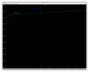
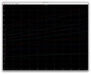
After I posted about this, I tried it on that 3055 model that is missing a lot of parameters. That one was giving out totally flat, horizontal curves for Ic/Vce, and it is also showing almost no curve at the knee.
After I added the VAF=150 parameters, that same sim for Ic/Vce looked more normal, with slanted curves.
This wouldn't be the case if VAF defaulted to 100, as with that value the curves would always be slanted, but when missing the VAF parameter, the curves are 100% horizontal.
I can only conclude VAF defaults to infinity and not some arbitrary value.
If you look at the Q section of Elements in the LTSpice manual, it will list all the default values. This is preferred because it allows a person to quickly do some experiments with the blank NPN and PNP models and get reasonable results.
I couldn't find this. I collected many documents, tutos, guides, whatever, and couldn't find this particular part.
Anyway, this would make sense, and I don't know about all the parameters, however, for this one, VAF and likely it applies the same to VAR, this default doesn't seem to apply. The actual tests say otherwise.
Ic/Vbe very closely follows an exponential function, Vaf only shifts Vbe.
Yes, but if the resulting curve is totally flat, then what does this mean?
Which parameter determines where the knee is and what about the part before that knee, towards 0 on both axis?
The curve you see in the datasheet is Ic vs Vce, not Ic vs Vbe.
This page is in the LTspice help file:
http://ltwiki.org/index.php?title=Q_Bipolar_transistor
This page is in the LTspice help file:
http://ltwiki.org/index.php?title=Q_Bipolar_transistor
Last edited:
The curve you see in the datasheet is Ic vs Vce, not Ic vs Vbe.
Yes, my mistake, that's what I meant, and that's what my little jig traces from the models.
I had horizontal curves with that shaky model, then when VAF was added, the curves looked more "normal".
You are confusing saturation with Early voltage. The knee is saturation behavior, Early voltage only determines the slope of the line above the saturation point. Positioning the knee involves adjusting the saturation currents for the collector and emitter diodes as well as the quasi-saturation parameters, but will hardly be affected by Vaf.
Higher Early voltage makes the Ic/Vce slope flatter, more like a CCS and less like a resistor. Generally higher is better, since Early effect reduces the voltage gain at the collector. More Vaf means less Early effect.
Higher Early voltage makes the Ic/Vce slope flatter, more like a CCS and less like a resistor. Generally higher is better, since Early effect reduces the voltage gain at the collector. More Vaf means less Early effect.
Last edited:
You are confusing saturation with Early voltage. The knee is saturation behavior, Early voltage only determines the slope of the line above the saturation point.
I wasn't confusing those things. But they are effects showing up on the same curves.
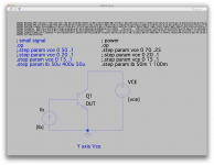
I attached a shot of the little test jig that I used to check this Ic/Vce (not Vbe), and I stopped the sim early to see enough of one curve being traced, with the knee visible (circled red). I also put a blue line parallel to the curve, which is the slope of the early voltage. That arrow pointing in the direction where eventually that slope will intersect with the x-axis, and at that point is the value of VAF.
Obviously this should be a negative value, but I guess for VAF in spice we use only absolute values. The VAR would be the opposite and a positive value.
That jig allows quick and easy switching to various models using :ako, and the device under test here is that overly simplified ST model of the 3055.
It didn't have a VAF parameter, so there was no slope at all for the early voltage. It was totally horizontal. This would mean the default for VAF to be infinite and not a fixed arbitrary value.
With that VAF at 150, if I let the whole sim run, we get that other plot with all the curves slanted.
Higher Early voltage makes the Ic/Vce slope flatter, more like a CCS and less like a resistor. Generally higher is better, since Early effect reduces the voltage gain at the collector. More Vaf means less Early effect.
Flatter, to the point of totally flat, when VAF isn't there, thus infinite.
At least that's the result I got from that simulation.
I would interpret a higher VAF as "more linear". Is that it?
As I can see in a lot of models, the VAF is rather low and seems to be they're not very realistic. The real thing must be better, most of the time.
One other thing I noticed in that ST 3055 (bad) model, is the RE parameter, kind of looking like the better model, but with 2 more zeroes after the "."
Funny thing is, most of the parameters present in that short model pretty much match those in an other more complete ST model, which is also not so good, but better, with more parameters. And that one has VAF=90, a bit closer to reality.
VAR=30 though, is this anywhere near reality?
Attachments
What are the spice model parameters that determine the Ft?
I suspect it's not something given as a frequency but rather a time/delay or something like that.
If we look into those 3055 models, would be find them to represent the older and slower originals or the newer faster ones?
That would mean if we want to simulate things with both the old and new parts, we would really need more than one model for sure.
The modpex onsemi models are likely to be made for the newer parts, so logically the Ft should be some 2.5mhz or more.
What are the spice model parameters that determine the Ft?
I suspect it's not something given as a frequency but rather a time/delay or something like that.
If we look into those 3055 models, would be find them to represent the older and slower originals or the newer faster ones?
That would mean if we want to simulate things with both the old and new parts, we would really need more than one model for sure.
The modpex onsemi models are likely to be made for the newer parts, so logically the Ft should be some 2.5mhz or more.
hi spookydd,
I think you need to read the two chapters on SPICE in my book
") .
.cheers,
Bob
Really? TF for Ft? How imaginative
But looking at this in the BD139: TF=585e-12
This can't be a frequency, so as I suspected, something else is used, like a time. But this value with e-12 seems very small for a time though. Is the BD139 that fast?
Assuming this would be a time, in seconds. Then it couldn't be the length of a period, as that would be a frequency of a bit more than 1.7ghz.
Has to be something else.
But we're getting there...
new
I had to increase tf and Cjc/Cje to model an old RCA 2N3055
is that old model fairly close to the real thing?
I think you need to read the two chapters on SPICE in my book
Why didn't I think of that?
So much reading to do. Good suggestion, I'll do that. I likely won't be able to understand it all, but anything that adds to my knowledge is a plus. Thanks Bob.
You are right about the default value of Vaf, that is not what I am referring to.
The Ic/Vce curve doesn't represent how a device will behave in a real biased circuit. It generates a straight sloped line, but in most biased circuits the line will be flat and the difference will come nonlinearly out of Ib or Vbe. If you want to see this, make a 2-transistor CCS and sweep the voltage at the output while watching Vbe and Ib. Ib will fall as Vce rises.
On the Ic/Vce chart perfectly flat would be ideal and would be most linear, meaning high Vaf and constant Hfe regardless of Vce.
Tf is the electrical transition time of the physical chip, smaller is faster. There is no Ft parameter. Ft is determined mostly by Cje and Tf. Modeling of Ft changes with Vce and Ic are added with Vtf, Itf, Fc and several other parameters you can look at in the helpfile page I linked to.
Whenever I see MODPEX I brace for the times ahead.
Hi Spookydd
You are missing a 2pi.
That's because omega isn't a frequency but rather an angular frequency. Of course, I should've caught that. I was just doing the 1/f thing...
Take Bob's advice and read up on spice.
Sure thing!
- Home
- Design & Build
- Software Tools
- Spice simulation