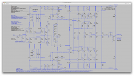
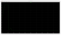
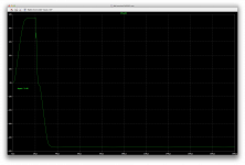
Here is a photo of an ON Semi 2N3055 operating at 200mA swept up to 90V.
The red line is my simple gradient detector and fitting the parameters to this gives VAF=181V.
Some difference.
WOW! Right you are!
So I guess we can just grab 180 and stick this in a model being tweaked, so we can get one step closer to a representative one.
One interesting thing at the same time, is the fact that you pushed it well beyond its rated 60V breakdown limit, and it's still fine, so that part has at least that much available, maybe even more. If a large number of parts in lots are that way and they're properly screened for this, as they're being matched, this can go into amps with a little higher rails.
We have so many more parameters to tweak this way...
I dug out one more model that was posted by Jan Didden some time ago for the 2n3055.
Comparing it to the others, it departs even more from a consensus.
That model has the highest VAF at 100, which may likely be nearer to the truth.
However, it has a BF of 360, which seems to be very excessive for the 3055. Compared to the others, 73 for the ST models, and 199.697 for the modpex 2n3055a, and 129.119 for the other modpex 2n3055g (h).
According to what I found about what the parameters are, BF being called ideal maximum forward beta, I assume this would be the maximum possible hfe, which according to the ST datasheet, could be anything from 50 to 250 (depending on group), and a datasheet from onsemi states it at 70.
So among those 5 models, the closest to a fairly representative, as far as max hfe is concerned, would be the ones from ST, with the BF=73.
One other parameter that varies hugely is IS:
IS=2.37e-8 for the ST models
IS=7.56605e-11 for the modpex 2n3055a
IS=2.37426e-14 for the other modpex 2n3055g
IS=4.66e-12 for the model posted by Jan Didden
So different. And that's just a few important parameters. The same thing is true on most others, not to mention some parameters not being present in some models, and the ST model having far too few of them to be any good.
Can we fix this?
I was trying to look up what IS would need to be. It depends on what they mean by saturation current, but I would assume it's the base current required to saturate the device, and this depends on voltage on vce, so that couldn't be a simple number, so I assume this parameter must have at least one other sibling that defines something else like a slope, and perhaps one for a knee or some roll off.
The datasheets really aren't too detailed, and we need more that what they provide to come up with all those parameters.
There is a lot of information on these parameters in the LTspice modeling chapter in my book, including definitions of all of the important SPICE parameters and actual procedures for generating models based on device measurements and or spec sheet information. IS is essentially the saturation current of the base-emitter junction. For a diode, IS, sets the amount of Vbe at a given current. Its value in different models can vary a lot, and it can also vary a lot in actual parts from different manufacturers. Vbe at a given collector current will increase by about 60mV for each decade of reduction of IS. If you run the output transistor at 100mA and measure Vbe, you can then do a SPICE run of that setup and tweak IS in the model to get about the same Vbe at 100mA. This simple approach is not perfect, but it gets you adequately in the ballpark.
Cheers,
Bob
LTspice IV vs LTspice XVII plotting compatibility
Hey guys, I have a dumb question.
I have LTspice IV and LTspice XVII running on different computers. If I take a ready-to-run circuit with its PLT file and its was created and plotted with LTspice XVII and I then try to run the circuit on LTspice IV, the thing does not plot.
Is there a plotting compatibility issue between LTspice IV and LTspice XVII?
Cheers,
Bob
I'm a little surprized that even a crappy model gives LTspice trouble, if I understood you properly.
Yes, lots of troubles, and swapping models cause different things, very weird.
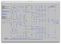
I was just running a sim on the super leach that I've been trying to get going with 3055/2955s, and this time with the MJ15015/16 substituted for the 3055/2955. Using AKO instead of swapping models directly in the schematic, so the schematic still shows the 3055/2955s, but they are running off the MJ models instead.
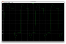
And the result is similar, very crazy. Posting this now so you can get the idea.
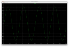
The sine wave is just trashed, and that output signal looks nothing like the input sine.
This gets better when lowering the input level, but it starts going crazy well before getting to maximum. And it happens at lower and lower levels as we go up in frequency.
The signal looks quite normal at 20hz and not too strong.
At some levels, the sine wave starts normal, and before one full cycle is done, there it goes...
I hardly changed the leach design, only tried tweaking a few things, but not so much. I tried keeping it with the values he defined.
Attachments
BTW, I'm guessing that it might not be too hard to dumb down models for those devices to sort of look like at least an approximation to the 3055 and 2955 devices that would at least behave in LTspice. The first thing to dumb down would be ft, via increasing Tf.
Probably nearly as much to do as trying to tweak the real models though.
And we don't have enough info to do so.
Those who can measure and know more about how to determine parameters could help with this.
It would be so much better to have models that are known to be good.
It takes a while to characterise a transistor to extract the Spice model parameters. I have certainly used higher VAF's than 30 which are probably derived from the 60V, 200mA Ic spec. which occurs near breakdown. As I have often mentioned, recent 2N3055's generally do have high BV. However, the basic SPICE models might not get quasi-saturation right at low voltage/high currents (reducing VAF) so this is another source of error. However, using an average value of VAF over the operating current range and not simulating the performance at low Vce's may get us somewhere close.
It takes a while to characterise a transistor to extract the Spice model parameters.
Sure, and that's why having more people collaborate can improve things.
As I have often mentioned, recent 2N3055's generally do have high BV.
But nothing guaranteed, so before using new parts on a design made to exceed the "normal" value, it would be better to test them first. They should be tested for matching anyway, if someone wants to do a decent job, so that extra test wouldn't add much to the rest.
The only thing is it's rather tricky to test for this in a non-destructive way.
However, the basic SPICE models might not get quasi-saturation right at low voltage/high currents (reducing VAF) so this is another source of error. However, using an average value of VAF over the operating current range and not simulating the performance at low Vce's may get us somewhere close.
Would you suggest using a value a little lower than 180 then? Maybe 150 perhaps.
Probably nearly as much to do as trying to tweak the real models though.
And we don't have enough info to do so.
Those who can measure and know more about how to determine parameters could help with this.
It would be so much better to have models that are known to be good.
Use my models for the MJL21193/4 and see if the amplifier behaves. If it doesn't, the odds are that there is something wrong with the circuit. Also, start off with conservative feedback compensation, like ULGF=500kHz. Moreover, probe all the nodes in SPICE to make sure the voltages are expected.
Cheers,
Bob
That looks like latching. When a VAS transistor saturates, the transimpedance can become negative, and then you have positive feedback, which can then lock up the amplifier if it doesn't resolve when it comes out of clipping. Try to find out which transistors don't return to a normal state when clipping stops. It is probably a VAS transistor model that is causing the problem. It might also have something to do with Q5 saturating in a way that allows another transistor to fully saturate, for instance. Some people who have experience with discrete latches and oscillators and logic circuitry might have the skills to identify the problem quickly.
Notice that Q14 and Q2 form the classic discrete SCR/latch/UJT circuit, which sometimes becomes self-aware in overload conditions and decides it hates your guts.
Notice that Q14 and Q2 form the classic discrete SCR/latch/UJT circuit, which sometimes becomes self-aware in overload conditions and decides it hates your guts.
Last edited:
Funnily enough, 150V is the value I have in my 3055 model.
Cool! Then 150 it is.
More such tweaks are required though. We need those better models.
What about the IS?
And BF?
Use my models for the MJL21193/4 and see if the amplifier behaves.
Actually I did that. And it's doing a lot better, however not perfect.
I wonder why the leach amps don't simulate well. The models are responsible for some troubles, but not all. How could such a proven amp design, that has been built over and over by so many people over a long time, not work properly when simulated? I don't get it. The models can't be the cause of all problems.
Besides, I've used those same models in other sims and they worked fine, kind of.
If it doesn't, the odds are that there is something wrong with the circuit.
The leach amp works in real builds, so it should work as well in sims.
Also, start off with conservative feedback compensation, like ULGF=500kHz. Moreover, probe all the nodes in SPICE to make sure the voltages are expected.
I always have a bunch of data labels all over the circuits in the interesting spots, and nothing seems out of place. It just behaves badly.
I've been looking for some calculation info in all of Leach's stuff to understand how his compensation scheme works and is calculated, without success. So I don't know what I should touch and how.
I did try tweaking the miller caps though, and that did help a little, but not completely.
I'm wary of touching his 2 feedback paths. He judiciously calculated that and since I don't know how, I don't dare touching it. It would likely have side effects if I did.
That looks like latching.
That was my first hunch, and that's why I thought about adding a baker clamp on the vas earlier, but it didn't change anything then.
It's quite possibly something like this though, and maybe made worse by the bad models.
Wouldn't those models cause similar issues in other sims as well?Try to find out which transistors don't return to a normal state when clipping stops. It is probably a VAS transistor model that is causing the problem.
I've been using those in many sims and this is the only one exhibiting this.
Maybe.It might also have something to do with Q5 saturating in a way that allows another transistor to fully saturate, for instance. Some people who have experience with discrete latches and oscillators and logic circuitry might have the skills to identify the problem quickly.
We are referring to the issue in the super leach with the 3055s right?
I kept the same part names in the sim as he named them in his docs (leach), so Q5 would be the cascode in the positive side ltp then.
I'm posting 2 tests with 2.2V and 2.4V input levels. The 2.2V works fine (20khz), and 2.4V drives it nuts.
Wow! I wouldn't have seen that. How does this work?Notice that Q14 and Q2 form the classic discrete SCR/latch/UJT circuit, which sometimes becomes self-aware in overload conditions and decides it hates your guts.
By the way, just to make sure, although the sim schematic I posted shows 2N3055 and MJ2955, the models used in those sims are actually the MJ15015/16. Behavior is even more erratic with the actual 3055/2955 models.
One other thing. The rails may be at 60V, but the peak of the output signal isn't even close to 50V, so I doubt this would be triggered by clipping on the outputs.
Attachments
Last edited:
If you make a model you should know the manufacturer of the transistor being modeled, because transistors can be very different between manufacturers.
True. I can use a model from either ST or a modpex one as a base and apply tweaks. But in the end, the datasheets are mostly in agreement between manufacturers though.
We can have a generic model, kind of average, with the most typical values.
Some may prefer having several models to test things, but it gets complicated to switch between them.
A typical model that reflects most available devices is all we need.
Do you have models of 3055/2955s known to work?
I swapped again the models on the super leach to the MJL21193/4 from Bob's library, and get the same sticking issue with high level (not clipping) signals.
Something must be wrong with some other models maybe, or something particular about the leach design may bring up some odd behavior that only happens in this topology...
Still can't get it to work properly. Shouldn't it work as is, out of the box, with leach's calculated values?
Oh boy! He must be rolling over in his tomb, as we're talking about him so often. I just wish I had been one of his students. It would've been so interesting..
I've been looking for some calculation info in all of Leach's stuff to understand how his compensation scheme works and is calculated, without success. So I don't know what I should touch and how.
I did try tweaking the miller caps though, and that did help a little, but not completely.
I'm wary of touching his 2 feedback paths. He judiciously calculated that and since I don't know how, I don't dare touching it. It would likely have side effects if I did.
From what I see the feedback does nothing more than switch the feedback point to the predrivers at the cutoff frequency shared by C8 and C9. This is actually a heavy compromise, probably because the 2N3055 of the day was too slow to be compatible with a fast feedback loop. The 2N3055 we have today may be totally different depending on who you get it from.
At RF, feedback has to be taken before the outputs because they have too much phase shift which will cause positive feedback. However when the feedback point is no longer the output, the distortions in the stages past the feedback point no longer get corrected. So this results in more distortion.
Visualize the feedback network as a crossover network, starting at the negative LTP input and R17 and R20 going to drivers. The basic concept is the same, although it works a bit differently.
A more modern way of getting around this problem would be transitional miller compensation (TMC), which could be used at the negative LTP input and/or at the VAS.
That was my first hunch, and that's why I thought about adding a baker clamp on the vas earlier, but it didn't change anything then.
Sometimes discrete quirks don't follow the generally known patterns, and creative solutions must be devised. It is educating to inspect each transistor for saturation at points along the waveform until you figure out exactly what is happening and why.
It's quite possibly something like this though, and maybe made worse by the bad models.
Wouldn't those models cause similar issues in other sims as well?
I've been using those in many sims and this is the only one exhibiting this.
No, latching is caused by a reversal of gain / positive feedback, something that won't happen if the model parameters are anywhere near correct. With multiple transistors interacting the small quirks can be amplified, but generally even if the models are exaggerating it, if there is a tendency to latch in simulation there will probably be the same tendency, even if suppressed, in the real prototype.
Maybe.
We are referring to the issue in the super leach with the 3055s right?
I kept the same part names in the sim as he named them in his docs (leach), so Q5 would be the cascode in the positive side ltp then.
Same part names, but your parts could still be very different than the parts he had.
I'm posting 2 tests with 2.2V and 2.4V input levels. The 2.2V works fine (20khz), and 2.4V drives it nuts.
When clipping first occurs, the VAS usually saturates first. If the input is driven any further, the transistors driving the VAS also begin to saturate. So you can have conditions where slight clipping is no problem but when you push it a certain amount past clipping all hell breaks loose.
Wow! I wouldn't have seen that. How does this work?
There are some articles on the web about how UJTs work, although they don't usually go into details on the exact conditions required for the discrete UJT to latch and how you would set that point intentionally. But generally latching happens when the base feeds of the discrete UJT are both current limited such that the transistors begin to drive each other rather than perform the separate tasks they were intended to. This is probably far too general so I suggest you try to find a webpage about it. People who design speaker protection relay circuitry can probably explain it to you.
One other thing. The rails may be at 60V, but the peak of the output signal isn't even close to 50V, so I doubt this would be triggered by clipping on the outputs.
Without having the simulation, my hunch would be that at full output Q14 is pulling a lot of current through Q24 who's Ib is causing the output cascode voltage to sag against those 6.2k resistors. This lowers the base voltage of the VAS cascode so that the clipping point is lower than it should be.
True. I can use a model from either ST or a modpex one as a base and apply tweaks. But in the end, the datasheets are mostly in agreement between manufacturers though.
There are so many more parameters in a model than in a datasheet. And sometimes the datasheets leave some things out or specify them at different operating points. Manufacturers often copy other manufacturer's datasheets but apart from the most basic specs, the real parts can be very different. Furthermore, some parts are older than my grandmother and the specification or at least the process used has been changed since then.
We can have a generic model, kind of average, with the most typical values.
Old versions of the 2N3055 were really terrible as I understand. A mid-way model could very well do poorly at modeling both the originals and the modern 'equivalent'.
Some may prefer having several models to test things, but it gets complicated to switch between them.
A typical model that reflects most available devices is all we need.
Do you have models of 3055/2955s known to work?
Modeling historical devices is a can of worms. I like to avoid using parts where someone who tries to build my circuit will get different results depending on where they get their parts. It saves a lot of headaches. I never use the 3055/2955 so I have never looked for models for them.
Last edited:
From what I see the feedback does nothing more than switch the feedback point to the predrivers at the cutoff frequency shared by C8 and C9. This is actually a heavy compromise, probably because the 2N3055 of the day was too slow to be compatible with a fast feedback loop. The 2N3055 we have today may be totally different depending on who you get it from.
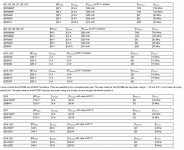
Actually the leach amp wasn't designed for 3055s to begin with. And they weren't even in his list of possible devices (see attached). But among the possible devices, there were the MJ15001/2/3/4, and those have a lot in common with the 3055.
I don't have it all still in mind, but from what I read about his compensation scheme, there is more to it. But it's true we could try replacing all of that by newer methods, including perhaps cherry as well.
At RF, feedback has to be taken before the outputs because they have too much phase shift which will cause positive feedback. However when the feedback point is no longer the output, the distortions in the stages past the feedback point no longer get corrected. So this results in more distortion.
And distortion there is. Surprisingly higher than I would expect from such a design. I was expecting nothing above about 100ppm at any frequency and level, but we're quite far from that. Maybe the models have something to do with it, but maybe not all. Perhaps a more up to date compensation might bring this amp to today's "standards".
A more modern way of getting around this problem would be transitional miller compensation (TMC), which could be used at the negative LTP input and/or at the VAS.
That's probably the first thing to try out instead of the leach designed comp scheme. And maybe, compare with cherry...
Sometimes discrete quirks don't follow the generally known patterns, and creative solutions must be devised. It is educating to inspect each transistor for saturation at points along the waveform until you figure out exactly what is happening and why.
I'd love to get to do that, but I'm not quite to that level yet, but I'm learning.
Same part names, but your parts could still be very different than the parts he had.
I made the effort, against ltspice's will, to keep the part names the same, for easier sharing and discussions. So unless I missed something, we can refer to the same part names from either the sim or schematic.
Without having the simulation, my hunch would be that at full output Q14 is pulling a lot of current through Q24 who's Ib is causing the output cascode voltage to sag against those 6.2k resistors. This lowers the base voltage of the VAS cascode so that the clipping point is lower than it should be.
I will clean it up and gather the models used, so I can post it.
In the mean time, I just swapped all of the vas and pre-drivers, the 2SA/2SC, with the BD139/40, and that changed nothing at all.
And then following on that assumption of the sagging cascode ref voltage, I figured I'd try a little brute force, so I disconnected a 6k2 on each side and put a 30V source there, which definitely nails that ref point down, with no more possible sagging.
And look at what happened!
There are so many more parameters in a model than in a datasheet. And sometimes the datasheets leave some things out or specify them at different operating points.
And that makes tweaking the models difficult to do. We have insufficient data. Plus without a full guide of what each model parameter means and how they can be determined from the available data in the datasheets, we're in the dark and guessing a lot.
Furthermore, some parts are older than my grandmother and the specification or at least the process used has been changed since then.
Well, she must not be quite that old then

I do have a nice bunch of old stock, and I better make sure not to mix those with newer ones when selecting parts.
Old versions of the 2N3055 were really terrible as I understand.
They were surely not what they are now. And I think the Ft back then was something like 800khz, at best.
At least I know that my old stock doesn't have any counterfeits, as that wasn't done back then.
A mid-way model could very well do poorly at modeling both the originals and the modern 'equivalent'.
Well, we don't need to have one model for all that, but maybe one mid-way for today's devices, at least from the most popular sources. We have ST, OnSemi, Central and perhaps a few more still producing them, but I suspect the most common would be from those 3.
My brain is starting to turn to mush, it's late for me in this time zone, so I'll have to call it quit for now and pick this up tomorrow, or it'll liquify and start oozing from my ears.
I'll clean the leach amp sim and gather the models used, for posting..
Attachments
Some guys have a way of making things sound far more complex than they really are, especially if they never talk about it to anyone except those steeped in the jargon of their chosen field. I think most of the math would have had to do with calculating the behavior of the amplifier stages, but choosing the feedback network would have been pretty basic after deciding on the crossover frequency.
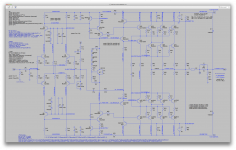
Notice that R20 = R17 + R18.
If you shorted C9 and removed C8, you would have feedback equally distributed among both feedback sources. This is probably intentional, otherwise you might get step response quirks when gain was higher or lower on either side of the crossover frequency.
Also notice that the corner frequency of C9 is the same as that of C8. C8 is ideally 4x C9, since that would make the corners match, but the designer stuck with common values.
At RF, where the danger of instability is present, no feedback comes from the output because it is shunted by C8. At RF we can also consider C9 a near-short. So what we have left for the feedback network at RF is plain miller compensation, along with a 22k feedback resistor to the predrivers. That's actually pretty boring. The only thing that happens in this feedback network is that at RF the feedback point is moved to a different node. There is no compensation for the individual stage phase shifts, they are just left where they are and the feedback point shifted almost as if to avoid dealing with them at all.
Some guys have a way of making things sound far more complex than they really are
We all have different levels of understanding. Some need more help than others to understand things better. That's what the sharing is all about. All good.
Notice that R20 = R17 + R18.
Now that you mention it, of course.
So what we have left for the feedback network at RF is plain miller compensation, along with a 22k feedback resistor to the predrivers. That's actually pretty boring. The only thing that happens in this feedback network is that at RF the feedback point is moved to a different node.
The feedback loops are nested this way. We don't see this often, not beyond the common miller loop, always nested within the global outer loop.
What I find odd is that such an old and proven design, that's definitely known working for real, and built by many, isn't working properly in simulation. How come? It can't all be because the models are crappy. Something else is going on.
Anyway, I think I got the sim cleaned up and gathered in its own folder with hopefully all its parts included to run out of that box.
Attaching the zip now.
Attachments
- Home
- Design & Build
- Software Tools
- Spice simulation