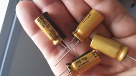
I hooked up the FX8 with the above mods. So the 50uF BP + 1uF film cap certainly made a difference - it's like a new amp for the better. Substantial improvement in perceived sound quality from standpoint of bass extension. Highs still clear and midrange has amazing fluid like smoothness and clarity. Dynamics have improved too - overall this has been the Bomb of a mod. I am going to give more time to sink in, but first impressions with about 4 songs so far have really impressed me. Definitely a super amp
I am not sure if the 4.7pF made a difference but certainly this amp has very clear percussive and transients are very sharp and clear.

1. You could try using 10uF nichicon 'muse' Bi-polar (datasheet claims "suited for audio signal circuits").http://www.mouser.com/ds/2/293/e-ues-876267.pdf .
2. Did you use 1000uF 16V cap for the 100uF 63V on the Sonal's layout.? "C7"
Last edited:
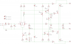
Here is the reference schematic on which my build is based and also sonal's layout. you could mark up your changes in paint.
reg
prasi
Attachments
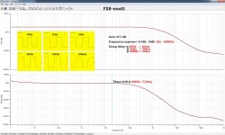
Some parameters
That's a TINA plot - can you please share TINA file?
How do you increase the VAS current? I accidentally played it with R9 being set at 2.2k vs 22k and maybe I am imagining it but it sounded very effortless yet powerful. I realized my mistake in reading the 5 band color code and swapped back to 20k. But when that 2.2k was in - it did not sound for the worse at all.
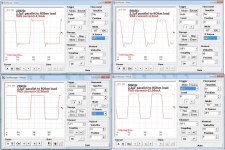
Until xrk's schematic will arrive I share the latest simulation of my FX8 mod, which shows excellent result. If I increase the VAS current from 4,3mA to 13mA FX8 can handle capacitive loads incredibly good. How is it possible?
That's pretty impressive square wave driving a capacitive load. I actually have other (non audio applications) where this is useful. Let me update schematic with what is actually built. If I get TINA file I can do it directly rather than markup in paint.
I would ask what method you are using to compare the changes you have made? Are you leaving one channel unchanged while you mod the other so you can accurately compare them?
Also, why are you using the headphone output rather than the line out?
Ha ha - headphone out so I have volume control - hence why I want to build PX6 preamp.
I did both channels and can easily go back and measure speaker response with calibrated mic - but it was unmistakeable that a good amp became a super amp with the change. Very much apparent by listening. This relates to my earlier question of how to quantifiably measure amp performance which no one has responded. I am all for actual measurement of performance. It is important for speakers and similarly should be important for amps. I am just new to amp building so don't have the scoop yet. I think it may be as simple as adapting my sound card to read voltage generated across dummy load and examine frequency response and HD as if it was a "loop back" test using REW.
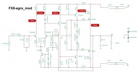
Here is my latest. TINA file attached.
Thank you! This does not have the potentiometer in it like the one I had made based on the Gerber files provided by Prasi. Would it be possible for you to model the 5cm x 5cm FX8 with potentiometer?
Thanks,
X
The board I am using is based on this file:
http://www.diyaudio.com/forums/soli...imate-fidelity-amplifier-651.html#post4641314
And the schematic is here as given by Prasi above:
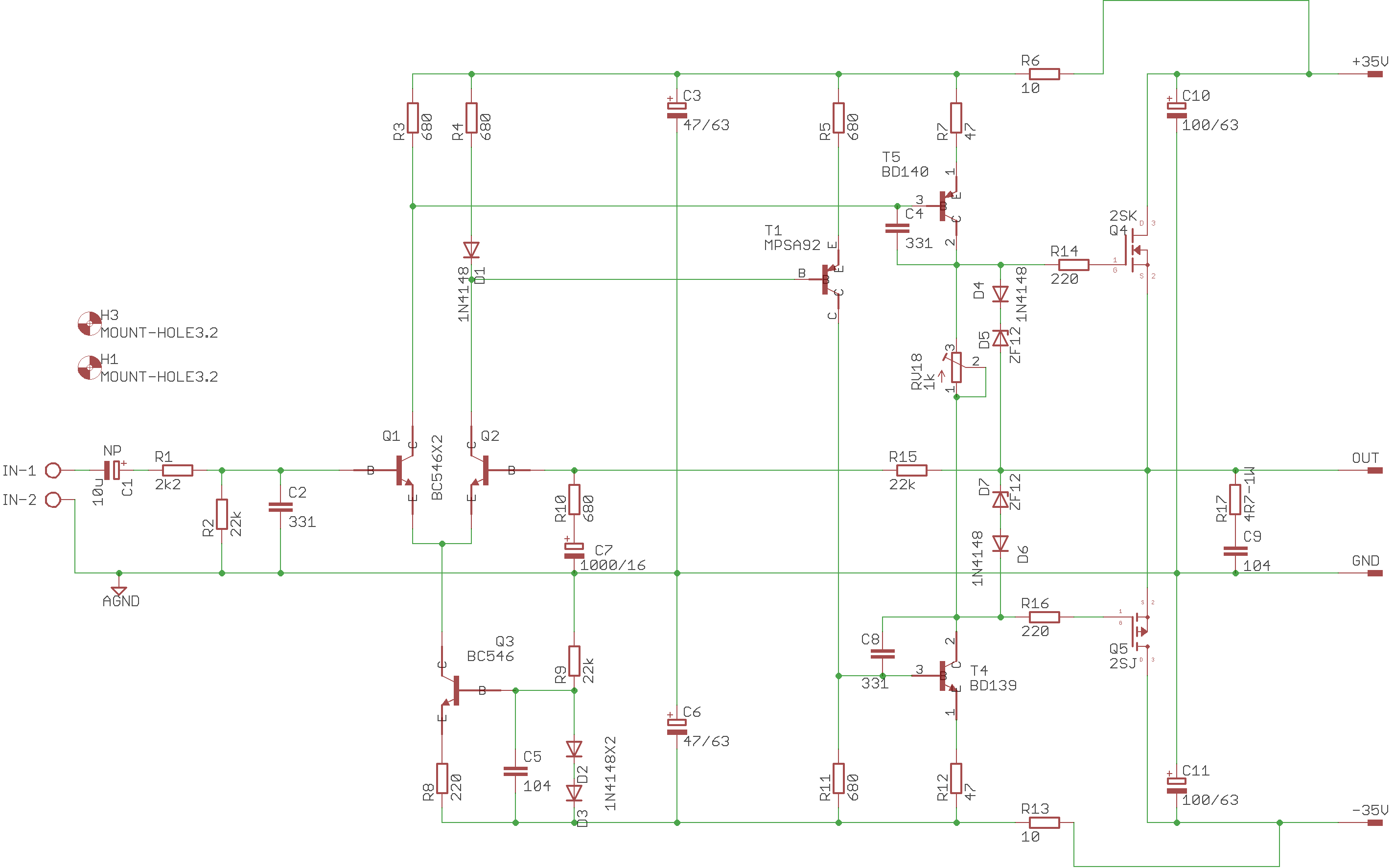
I will take a crack at putting this schematic into TINA but am new and slow.
My amp uses 51uF on input cap and all 22k resistors are swapped out for 2k. I also have 4.7pF across R15. R10 is 550ohms. Otherwise the same. I am indeed using 100uF 63v cap and all 47uF caps are 63v rated.
Last edited:
That's a TINA plot - can you please share TINA file?
How do you increase the VAS current?
Decrease the 180 Ohm in the current source of LTP and then correct the collector resistors.
Thank you! This does not have the potentiometer in it like the one I had made based on the Gerber files provided by Prasi. Would it be possible for you to model the 5cm x 5cm FX8 with potentiometer?
Thanks,
X
The board I am using is based on this file:
http://www.diyaudio.com/forums/soli...imate-fidelity-amplifier-651.html#post4641314
And the schematic is here as given by Prasi above:
I will take a crack at putting this schematic into TINA but am new and slow.
My amp uses 51uF on input cap and all 22k resistors are swapped out for 2k. I also have 4.7pF across R15. R10 is 550ohms. Otherwise the same. I am indeed using 100uF 63v cap and all 47uF caps are 63v rated.
Why on earth are you are you making all these changes when you have already said you don't understand the circuit? You can't change all the 22k resistors for 2k and expect anything to work. Where did you get the idea to use 51uF for an input cap? Did you just have one laying around?
Resistors are a penny a piece. Use the correct ones.
22k's are on order - they are not a value provided when buying a kit of assorted values from 10R to 1M. I changed the input caps after asking a few questions and Jay suggested the value I believe. Remember the whole NP vs BP discussion? The 4.7pF was Egra who mentioned that Bimo had a sim where overshoot on square wave would be reduced. The 2.2k was pure mistake on my part (as I clearly stated that I read the 5 color bands incorrectly) and subsequently went back to 20k. That was just one resistor (the one on the bottom right), all 22k's substituted with 20k, not 2k. It's like using 10% resistors.
Hey, this is diy and we are free to experiment for learning and for fun. Worst thing is we burn some components right? But sometimes by chance we find a result that happens to be good. You might want to try that 50uF BP cap mod for yourself.
Hey, this is diy and we are free to experiment for learning and for fun. Worst thing is we burn some components right? But sometimes by chance we find a result that happens to be good. You might want to try that 50uF BP cap mod for yourself.
Last edited:
Yes, this is DIY, but before doing any experimenting, i feel one should build according to designed/working sch, and then take experimentation further. one thing that u should first do, is to change all 22k res to 22k and 100u63v to 1000u/16v. you never know, the treasure is hidden in original map (schematic)22k's are on order - they are not a value provided when buying a kit of assorted values from 10R to 1M. I changed the input caps after asking a few questions and Jay suggested the value I believe. Remember the whole NP vs BP discussion? The 4.7pF was Egra who mentioned that Bimo had a sim where overshoot on square wave would be reduced. The 2.2k was pure mistake on my part (as I clearly stated that I read the 5 color bands incorrectly) and subsequently went back to 20k. That was just one resistor (the one on the bottom right), all 22k's substituted with 20k, not 2k. It's like using 10% resistors.
Hey, this is diy and we are free to experiment for learning and for fun. Worst thing is we burn some components right? But sometimes by chance we find a result that happens to be good. You might want to try that 50uF BP cap mod for yourself.
Ok, but the map printed on the silkscreen says 100uF 63v.
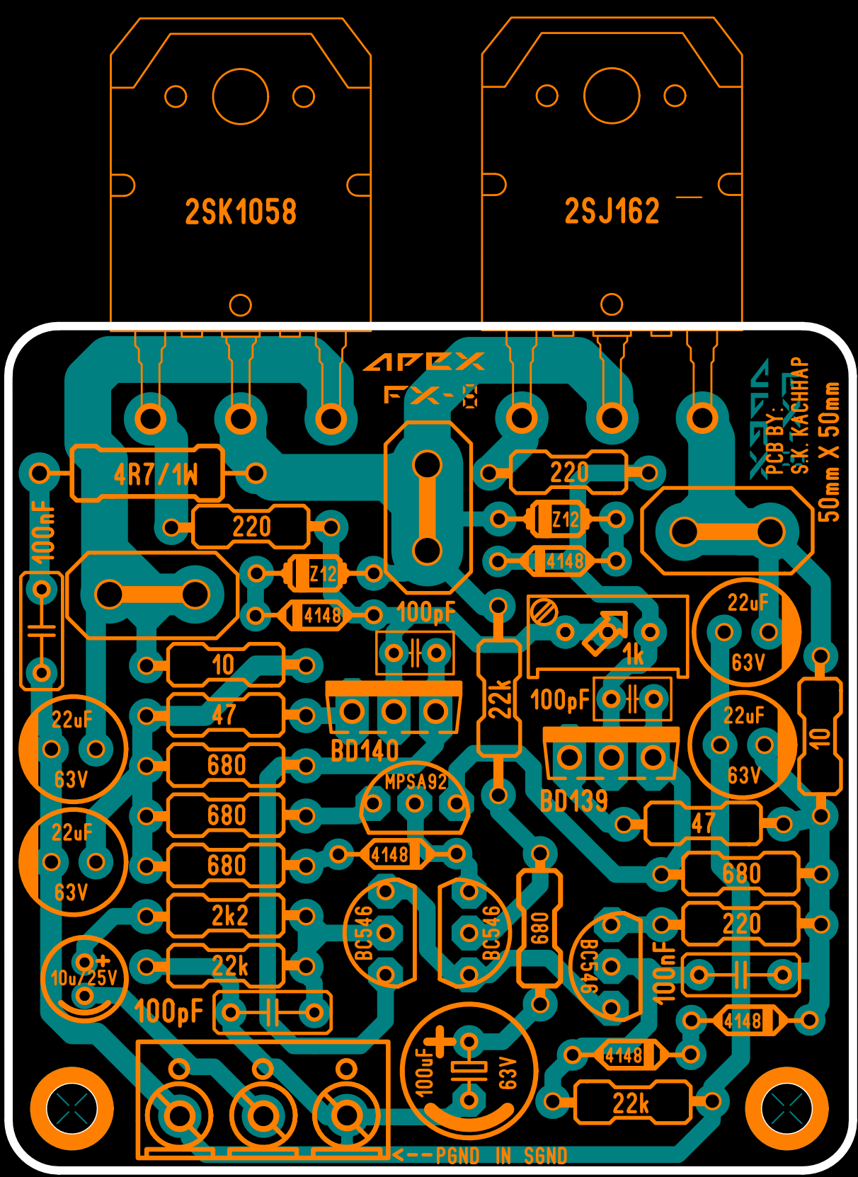
100u63V is the min that you can use ...., but to have accurate sound (based on measurements by Terry), I have said at least in two posts and Mr. Miles in one post originally and Terry in his test... "To improve 50Hz response, you use 1000uF16V". I had recommended to you directly in one of the post, if memory serves right. and also to Benz!
reg
prasi
Ok, but the map printed on the silkscreen says 100uF 63v.
The original value for that cap is 100uF but no voltage limit is listed. That cap sees less than one volt so even 6.3V is fine. Apex suggested going to the 1000uF to improve the 100hz square wave which it did. Sonal put 63V there but I think is was just because that is what the Sprint macro he used had.
OK, 1000uF going in there tonight. Thanks - sorry I missed the note to use as big as possible there.
yes sir. even sonal stated, when he posted layout ... http://www.diyaudio.com/forums/soli...imate-fidelity-amplifier-649.html#post4635579
- Home
- Amplifiers
- Solid State
- 100W Ultimate Fidelity Amplifier