Absolutly right.!")
Question is : how much and how close to thermal limit are you running your output transistors....?
Can you put numbers on that ?
I am not saying it will not add to thermal resistance but i question how significant it is if you do it right.
Absolutes are dangerous.
how can I explain simply, so, mosfet's heat must be around 55 celcius for good sound (as my experience). And its heat can change up quickly. for linear heat transfer, should not put any thermal resistance between mosfet and cooler. If you cannot keep heat under control, you cannot take good result " absolutely"
Question is : how much and how close to thermal limit are you running your output transistors....?
Can you put numbers on that ?
I am not saying it will not add to thermal resistance but i question how significant it is if you do it right.
Absolutes are dangerous.
The real question is how close or outside the devices SOAR will you get when you bias the device at the recommended level ?
Let's not forget bias level, heatsink efficiency, thermal stability, and thermal interface are all inter related.
Nice artwork!
If you build your own boxes you may even go for a dual mono setup. This can give more options with placing them.
Also you may want to consider to have two filter caps close to the boards - or even double the PSU Boards and move them to the amp boxes entirely.
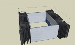
A little change in the chassis. I modeled it with the Galaxy 280mm x 230mm 3U chassis and bolt my heatsinks directly to the quasi-heatsinks.
I've got 8x22Kuf caps in the psu chassis. How many caps should go in the output chassis? The umbilicals will only be six inches or so between the PSU and the output chassis.
Attachments
An advice;
Dont place any aluminium sheet, between cooler and mosfets.
But separately PSU is good idea.
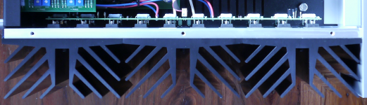
This is pass labs XA30.8 Amplifier .There is an Aluminium sheet between MOSFET s and Heat Sink .
Attachments

This is pass labs XA30.8 Amplifier .There is an Aluminium sheet between MOSFET s and Heat Sink .
That's not a sheet. It's a thick slab. Basically part of the heatsink.
Grounding in a two chassis solution
I've been reading the F5 and F6 build guides over and over again to help minimize my chances for mistakes.
In this F5 build guide thread, AndrewT and 6L6 talk about how to star ground 6L6's F5. How would you implement a quasi-star ground in a two chassis solution? Would you put a grounding post on the power supply chassis and put a grounding post in the output chassis so that you could connect the PSU ground to the output circuit board ground? Or am I just overthinking all of this?
I'm using Neutrik PowerOn connectors and they have three contacts so I could implement (+), (-) and (chassis ground) conductors in my umbilical.
as much you can squeeze in
actually, why?
I reckon the last cap near the board would suffice or a decent size extra cap. Anything between the exiled filter bank and the domestic cap counts as R and L giving some extra ripple suppression.
Keeping the caps in the cool box wouldn't harm either.
I've been reading the F5 and F6 build guides over and over again to help minimize my chances for mistakes.
In this F5 build guide thread, AndrewT and 6L6 talk about how to star ground 6L6's F5. How would you implement a quasi-star ground in a two chassis solution? Would you put a grounding post on the power supply chassis and put a grounding post in the output chassis so that you could connect the PSU ground to the output circuit board ground? Or am I just overthinking all of this?
I'm using Neutrik PowerOn connectors and they have three contacts so I could implement (+), (-) and (chassis ground) conductors in my umbilical.
I used the power cons in my F-5. It is dual mono including two power cords. Just build it exactly like 6l6 did in his build thread. The IEC has 3 poles, just like the power con. Easy peasy. As far as the boards ground connection, I did it just like Peter Daniels did it. Apparently this isnt the "approved Method" and 6L6 said that way was a little more quiet. Mine makes no noise or hum at all, so I left it as was.
Russellc
Last edited:
This is pass labs XA30.8 Amplifier .There is an Aluminium sheet between MOSFET s and Heat Sink .
Something was needed to hold all those separate Fin extrusions together.... likely Ali because Copper would have been Too expensive
To Marc Brown: Using a PowerOn, connect (+), (-), (G or common). You do not need to run earth to the amp chassis. I did a dual mono using a SpeakOn (no high voltage AC here) to each channel and ran +, G, -, G (there are 4 conductors) with a 12-4 cable. I connected the amp chassis to G but did not notice any difference. The G of each channel is connected to earth in the PS chassis though the CL-60 paralleled with a 35 A bridge rectifier (as F5T manual and 6L6 show). Also, follow Zen Mod's advice with space and cost being the limiting factors. I put 54 mF per rail per channel near the amp PCB with a large CLC back in the PS chassis, and it is dead quiet. You may try moving the PS chassis away from the amp chassis to see if it sounds any better (quieter).
That's not a sheet. It's a thick slab. Basically part of the heatsink.
It is not part of the heatsink it is a heatspreader to assure that the heatsinks dissipate the heat as uniformly as possible.
I would also call your attention for the " L " brackets NP sugests for the new SONY VFET amp as a heat transfer means to the heatsinks.
Once again : "stay away from absolutes" and use good judgement.
Engineering is compromise.
Good words "Engineering is compromise"
I know what you try to tell and theorical your right "absolutely" . it was joke
However, you think about factory production conditions. But our friend will does DIY. For me, full contact thin aluminium sheet and cooler is so difficult and he wouldnt do. Maybe compound can helps but in time it will need to refreshing. Disassemble all part and again assemble, bla bla... So i said to avoid from sheet.
Engeenering is foresight and optimization also.

Last edited:
Good words "Engineering is compromise"
I know what you try to tell and theorical your right "absolutely" . it was joke
However, you think about factory production conditions. But our friend will does DIY. For me, full contact thin aluminium sheet and cooler is so difficult and he wouldnt do. Maybe compound can helps but in time it will need to refreshing. Disassemble all part and again assemble, bla bla... So i said to avoid from sheet.
Engeenering is foresight and optimization also.
Said like that i agree....thin alu sheet will not work because contact area with heatsinks will be very irregular.
As always the devil...and Murphy is in the details.....
To Marc Brown: Using a PowerOn, connect (+), (-), (G or common). You do not need to run earth to the amp chassis. I did a dual mono using a SpeakOn (no high voltage AC here) to each channel and ran +, G, -, G (there are 4 conductors) with a 12-4 cable. I connected the amp chassis to G but did not notice any difference. The G of each channel is connected to earth in the PS chassis though the CL-60 paralleled with a 35 A bridge rectifier (as F5T manual and 6L6 show). Also, follow Zen Mod's advice with space and cost being the limiting factors. I put 54 mF per rail per channel near the amp PCB with a large CLC back in the PS chassis, and it is dead quiet. You may try moving the PS chassis away from the amp chassis to see if it sounds any better (quieter).
Thank you for sharing your experiences, thoughts and insights. My reasons for building a two-chassis solution have evaporated as I sold my Aleph J boards to free up time and replenish DIY funds. So, back to Sketchup to update my design as a single chassis F6.

- Home
- Amplifiers
- Pass Labs
- The diyAudio Firstwatt F6