@ David McBean
Re - Error Showing ?
I see what you did there ! Now i know why often non English sost are different, it's the regional settings. No issue then. Thanx")
************
Re - Not always Easy !
Well i'm glad you said that, & i'm NOT being funny. Because that IS an actual design done with HR. Please see the design in Post # 168 etc here http://www.diyaudio.com/forums/subw...subwoofer-4ohm-special-run-cheap-ebay-17.html & the HR file that you posted in # 174
The drawing you kindly did in Post # 6136, looks nothing like in the above thread ?
So i hope you can now understand how difficult it is sometimes to translate a sim into an actual build, with HR. If we could have a, what you Actually see is what you'll Actually get, that make a HUGE difference, to me and Lots of others too. Have a think about it & veave your magic
Regards
Re - Error Showing ?
I see what you did there ! Now i know why often non English sost are different, it's the regional settings. No issue then. Thanx
************
Re - Not always Easy !
It's not a practical physical design - just because it can be drawn in the form shown, doesn't necessarily mean that it can be built.
Well i'm glad you said that, & i'm NOT being funny. Because that IS an actual design done with HR. Please see the design in Post # 168 etc here http://www.diyaudio.com/forums/subw...subwoofer-4ohm-special-run-cheap-ebay-17.html & the HR file that you posted in # 174
The drawing you kindly did in Post # 6136, looks nothing like in the above thread ?
So i hope you can now understand how difficult it is sometimes to translate a sim into an actual build, with HR. If we could have a, what you Actually see is what you'll Actually get, that make a HUGE difference, to me and Lots of others too. Have a think about it & veave your magic
Regards
Hi Zero D,
The post linked below appears to give further details of the design in question:
http://www.diyaudio.com/forums/subw...ld-series-tuned-6th-order-56.html#post4039252
That's because it is just the standard classic example of an object that can be drawn, but not physically built.
https://en.wikipedia.org/wiki/Impossible_trident
Hornresp has no idea what physical configuration the user has in mind when a system is simulated. The schematic diagram currently provided accurately reflects the inputs, and that is all that can be done. As the current case has highlighted though, it does help to know what the actual input values are, when trying to interpret some of the more envelope-stretching "escoteric" designs that creative diyAudio fanatics like 'Matthew Morgan J' and 'Patrick Bateman' keep coming up with.
Kind regards,
David
Please see the design in Post # 168 etc here http://www.diyaudio.com/forums/subw...subwoofer-4ohm-special-run-cheap-ebay-17.html & the HR file that you posted in # 174
The post linked below appears to give further details of the design in question:
http://www.diyaudio.com/forums/subw...ld-series-tuned-6th-order-56.html#post4039252
The drawing you kindly did in Post # 6136, looks nothing like in the above thread ?
That's because it is just the standard classic example of an object that can be drawn, but not physically built
.https://en.wikipedia.org/wiki/Impossible_trident
So i hope you can now understand how difficult it is sometimes to translate a sim into an actual build, with HR. If we could have a, what you Actually see is what you'll Actually get, that make a HUGE difference, to me and Lots of others too. Have a think about it & veave your magic
Hornresp has no idea what physical configuration the user has in mind when a system is simulated. The schematic diagram currently provided accurately reflects the inputs, and that is all that can be done. As the current case has highlighted though, it does help to know what the actual input values are, when trying to interpret some of the more envelope-stretching "escoteric" designs that creative diyAudio fanatics like 'Matthew Morgan J' and 'Patrick Bateman' keep coming up with
.Kind regards,
David
@ David McBean
I understand what the impossible trident image was now ! Very interesting.
Getting back to my enquires etc. Unless i'm mistaken, the posted design WAS translated from an HR sim, both shown here. Taken that as correct, if i had only seen the sim & i hadn't seen the sketch, i wouldn't have been able to fathom out how to translate it into a sketch and/or actual design & build. I wonder how many others would be stumped too ? Sure i know a few on here etc could do it, but that's not my point or wish. My wish is for HR to be more user friendly, in the manner i've illustrated.
Regards
Attachments
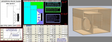
Unless i'm mistaken, the posted design WAS translated from an HR sim, both shown here. Taken that as correct, if i had only seen the sim & i hadn't seen the sketch, i wouldn't have been able to fathom out how to translate it into a sketch and/or actual design & build. I wonder how many others would be stumped too ? Sure i know a few on here etc could do it, but that's not my point or wish. My wish is for HR to be more user friendly, in the manner i've illustrated.
Hi Zero D,
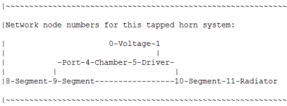
As indicated in my previous message, Hornresp is not a mind reader. The program has no way of knowing how the user intends to physically lay out his or her system. That's why 'Matthew Morgan J' produced his sketches in the first place, so that others could understand his thinking. What you are asking of Hornresp is simply impossible to implement. If you are having difficulty interpreting the Hornresp schematic diagram when also given the input parameter values, then perhaps the nodal diagram included in the AkAbak export script will help you to better understand the acoustic paths for a particular system - see attachment.
Kind regards,
David
Attachments
Hornresp Update 3970-160326
Hi Everyone,
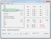
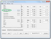
The code controlling the Undo and Redo menu commands was not updated to take into account the Hypex Approximator when the tool was recently added. This oversight has now been corrected.
A number of other Undo / Redo "loose ends" have also been tidied up. For example, double-clicking of the Fr / Tal, Ap / Lpt and Ap1 / Lp labels was not being registered. This has now been fixed.
Kind regards,
David
Hi Everyone,
The code controlling the Undo and Redo menu commands was not updated to take into account the Hypex Approximator when the tool was recently added. This oversight has now been corrected.
A number of other Undo / Redo "loose ends" have also been tidied up. For example, double-clicking of the Fr / Tal, Ap / Lpt and Ap1 / Lp labels was not being registered. This has now been fixed.
Kind regards,
David
Attachments
Rectangular Tractrix Simulation
Hello.
I'm designing my first horn along the lines of Bruce Edgar's 300Hz Tractrix and I'm getting confused along the way in how to use Hornresp.
I have selected a 5" cone driver: Faital pro M5N12-80, and I'm using Volvotreter's spreadsheet "Tractrix_v1.4b.xls". My understanding is the Excel spreadsheet is used to generate some inputs to Hornresp:
Thank you!!
Hello.
I'm designing my first horn along the lines of Bruce Edgar's 300Hz Tractrix and I'm getting confused along the way in how to use Hornresp.
I have selected a 5" cone driver: Faital pro M5N12-80, and I'm using Volvotreter's spreadsheet "Tractrix_v1.4b.xls". My understanding is the Excel spreadsheet is used to generate some inputs to Hornresp:
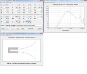
- On the "Rect. Horns by Driver TSP" tab I enter 282Hz as flare cutoff frequency since I'd like to use the horn from 400Hz. Aspect ratio of 2:1, and Thiele-Smalll parameters of the driver. See attached. I get a throat area of 21.3cm2 and mouth area of 1157cm2.
- On Hornresp I input:
- 2xPi angle
- M5N12-80 parameters
- Tractrix type, S1: 21.3cm2, S2: 1157cm2, F12: 282Hz, and let it calculate L12 to be 33.1cm (slightly longer than the spreadsheet's 32.5cm).
- Rear sealed chamber: 2 liters and 20cm long (guesstimate), with 4cm lining.
- Vtc I estimated in 200cm3 with the Hornresp utility, since I don't have the driver with me. And assumed Atc=Sd.
- Since Atc is 94.2cm2 and S1 is 21.3cm2 I asume I need a throat adaptor. Correct?
- If I don't use an adaptor the response is smooth. But it might be an artifact of a model that cannot be implemented in practice?
- If I use a 2cm adaptor going from Atc to S1, Hornresp shows a ragged response, and shows no lining on the back chamber. Not sure if the noise is introduced by the adaptor or lack of lining? I'm not finding a way to keep the sealed back chamber lined and also model an adaptor.
Thank you!!
Attachments

A little help.
I worked with those drivers quite a bit a few years ago and still think very highly of them.
Below is a set of measurements that I made. One of the drivers is tested twice.
You will find that when you enter the Thiele Small parameters directly into Hornresp that there will be a difference in the resulting simulation.
Next.
To what bandwidth are you wanting to use this driver?
The stated throat opening will indeed cut off the upper portion of the response.
Here is a possible alternative to the method you are using.
I do not know for certain that this is indeed correct. Perhaps someone can offer a correction if I am wrong in thinking that Hornresp will generate a Tractrix set of calculations in the manner that I am describing below.
But this is another method to generate a possible horn.
Enter your correct driver parameters.
On the tools tab in Hornresp click on System Design with driver. Enter your desired pass band. It will generate a Hypex horn. Go over to the calculate button and see the resulting response.
Now go back to the input screen and highlight the field to the right of Hyp. Hit the "T" on your keyboard and it will change the horn to a Tractrix design.
Hit calculate and use the compare tool to see the difference.
To generate a horn with parallel upper and lower walls you can do that in the File tab in the schematic window.
I don't think David has incorporated a upper and lower angled wall option when generating horns. That might be a worthwhile thing to ask for if it has not been addressed.
Attachments
A little help.
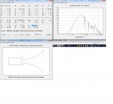
I worked with those drivers quite a bit a few years ago and still think very highly of them.
Below is a set of measurements that I made. One of the drivers is tested twice.
You will find that when you enter the Thiele Small parameters directly into Hornresp that there will be a difference in the resulting simulation.
Next.
To what bandwidth are you wanting to use this driver?
The stated throat opening will indeed cut off the upper portion of the response.
Here is a possible alternative to the method you are using.
I do not know for certain that this is indeed correct. Perhaps someone can offer a correction if I am wrong in thinking that Hornresp will generate a Tractrix set of calculations in the manner that I am describing below.
But this is another method to generate a possible horn.
Enter your correct driver parameters.
On the tools tab in Hornresp click on System Design with driver. Enter your desired pass band. It will generate a Hypex horn. Go over to the calculate button and see the resulting response.
Now go back to the input screen and highlight the field to the right of Hyp. Hit the "T" on your keyboard and it will change the horn to a Tractrix design.
Hit calculate and use the compare tool to see the difference.
To generate a horn with parallel upper and lower walls you can do that in the File tab in the schematic window.
I don't think David has incorporated a upper and lower angled wall option when generating horns. That might be a worthwhile thing to ask for if it has not been addressed.
Mark,
Thank you for the quick reply. Your measurements are significantly different from the Faital published data. I guess my best path forward is to use your measured data until I get the drivers and measure the ones I get. What do you recommend I use to measure drivers?
The Hornresp approach you suggested is yielding starnge results. The power response looks great, but the dimensions look unrealistic I think:
- S1: 3.8cm2 vs. Sd of 94cm2.
- Vtc of 3cm3...my estimation of the volume of air between cone and front is 200cm3. How could I get to 3cm3 having an Sd of 94cm2?
- Volume of rear chamber of 0.06 liters...
ARTA and a few resistors is pretty good.
ARTA Software
REW is also good. And it needs a few resistors as well.
REW - Room EQ Wizard Room Acoustics Software
Throat coupling chamber.
Many things have been worked out since Bruce Edgar wrote that article.
And Bruce Edgar himself used vastly different horns latter on.
ARTA Software
REW is also good. And it needs a few resistors as well.
REW - Room EQ Wizard Room Acoustics Software
Throat coupling chamber.
Many things have been worked out since Bruce Edgar wrote that article.
And Bruce Edgar himself used vastly different horns latter on.
ARTA and a few resistors is pretty good.
ARTA Software
REW is also good. And it needs a few resistors as well.
REW - Room EQ Wizard Room Acoustics Software
Throat coupling chamber.
Many things have been worked out since Bruce Edgar wrote that article.
And Bruce Edgar himself used vastly different horns latter on.
Good. I'm familiar with REW although for room acoustics. Will look into it.
What kind of horn would you recommend with this cone and to play 350 to 2500Hz? I prefer a rectangular mouth to reduce the distance to a tall tweeter (Beyma TPL-150H).
Would love to get high sensitivity to drive it with a SET 45 or 2A3 in a fully active setup.
Thank you!!
What kind of horn would you recommend with this cone and to play 350 to 2500Hz?
Would love to get high sensitivity to drive it with a SET 45 or 2A3 in a fully active setup.
To horn load to 2500 Hz requires a very high compression ratio and phase plug, so not a trivial design and the tiny rear chamber is nearly impossible to do, so will probably require tuning it with a TL.
With its relatively weak motor, a large throat is desirable, so while its horn loaded pass-band will be a bit more than its mid-band efficiency, it will have to be EQ'd to line up with whatever it's HF efficiency is. This will make its rear chamber large enough to barely fit the driver, so heat dissipation wise, it won't be able to handle a lot power without some compression.
GM
Attachments
I'm designing my first horn along the lines of Bruce Edgar's 300Hz Tractrix and I'm getting confused along the way in how to use Hornresp.
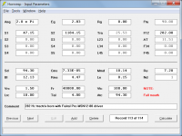
Hi LewinskiH01,
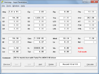
A possible design to get you started.
Assumptions:
Tractrix horn cutoff frequency:
Fc = 282 Hz
Driver parameters (from attached specification sheet):
Sd = 94.30 cm2
Re = 7.20 ohms
fs = 180 Hz
Vas = 0.93 litres
Qes = 0.59
Qms = 2.70
Le = 0.15 mH
Kind regards,
David
Attachments
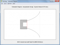
A possible design to get you started.
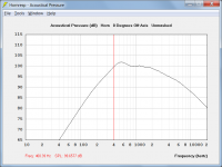
I should have clarified that efficiency was not a consideration.
Higher efficiency would require a throat area smaller than the driver Sd, necessitating a throat chamber.
Something like the attached design, for example.
Attachments
To horn load to 2500 Hz requires a very high compression ratio and phase plug, so not a trivial design and the tiny rear chamber is nearly impossible to do, so will probably require tuning it with a TL.
With its relatively weak motor, a large throat is desirable, so while its horn loaded pass-band will be a bit more than its mid-band efficiency, it will have to be EQ'd to line up with whatever it's HF efficiency is. This will make its rear chamber large enough to barely fit the driver, so heat dissipation wise, it won't be able to handle a lot power without some compression.
GM
It's the kind of rear chamber where you seal off the area around the basket side of the basket. And take you measurements from what you get in that situation.
It is useable. But requires a fair bit of work to make it so.
There are other sealed back midranges that are more suitable.
Hey Jan.
Norton was one of the candidates in the past to show "false alarm", thinking of hornresp as a virus of some sort. I am out of office right now, so I can´t take any actions. But to be 100% sure, throw the hornresp files into an online-scanner (which uses maaaaaany virus-scans at once), I am sure, no virus will show up
Norton was one of the candidates in the past to show "false alarm", thinking of hornresp as a virus of some sort. I am out of office right now, so I can´t take any actions. But to be 100% sure, throw the hornresp files into an online-scanner (which uses maaaaaany virus-scans at once), I am sure, no virus will show up
It's the kind of rear chamber where you seal off the area around the basket side of the basket. And take you measurements from what you get in that situation.
It is useable. But requires a fair bit of work to make it so.
There are other sealed back midranges that are more suitable.
Which midrange cone would you recommend for this? JBL CMCDs aren't available here, unfortunately.
Would sealing the basquet of the M5N12 get me into trouble in terms of thermal behaviour?
I should have clarified that efficiency was not a consideration.
Higher efficiency would require a throat area smaller than the driver Sd, necessitating a throat chamber.
Something like the attached design, for example.
Thank you David.
My tweeters are 104dB/W, so that would be the ideal sensitivity for these. I modeled the horn you posted (the one with S1=47.15cm2) and sensitivity looks good from 380 to 1400Hz (@103dB/W). At what compression ratio would you estimate I will start to need a phase plug?
Over at another thread a guy who's knowledgeable about horns hinted Hornresp will be accurate at the lower end, but might underestimate sensitivity drop at the higher end - meaning past 2000 Hz in my case. Would you agree with that? The sim is showing 100dB/W at 2500Hz.
BTW, my system is fully computer based with digital signal processing available, so eq is available. Of course I would rather trim as little as possible.
Which midrange cone would you recommend for this? JBL CMCDs aren't available here, unfortunately.
Would sealing the basquet of the M5N12 get me into trouble in terms of thermal behaviour?
What brands are available over there?
- Home
- Loudspeakers
- Subwoofers
- Hornresp