If such a horn (ie. designed against floor and one wall so that it is essentially acting like an axially quartered horn, CSA 1/4 at all axial points), could be modelled by using 4 drivers, and 4x actual CSA in free space then scaling the power.. in what other ways does this differ from modelling using the actual CSA and single driver in quarter space? Which would you choose?Hi Gisle,
Hi AllenB,
Plane wavefront model results, apart from electrical impedance, will be identical. Power does not have to be scaled if the multiple drivers are connected in parallel. You can readily confirm this for yourself:
1. Take a copy of the default record and set Fr and Tal equal to zero.
2. Take a copy of the above modified record, set Ang = 4.0 x Pi, multiply S1, S2, S3, Vrc, Vtc and Atc by 8, and set Nd = 8P (eight drivers in parallel).
3. Compare the results for the two records.
Electrical impedance will be different because in the first case we have a single driver, and in the second case there are eight drivers connected in parallel, so that the effective Re becomes 1/8 that of the single driver.
For the given plane wavefront example, I would most likely use the actual physical horn dimensions, with the single driver, radiating into 1/8 space, because this is what we actually have.
Note however, that when an isophase wavefront model is used, such as with a Le Cléac'h horn, there is no longer a linear relationship between the value of Ang and wavefront area because the wavefronts are curved. In Gisle's case, if 1.0 x Pi is considered to represent realistic loading conditions, then the Le Cléac'h horn should be simulated radiating into 4.0 x Pi space with 4 parallel-connected drivers, and then be actually built to 1/4 the dimensions specified in the simulation, and using a single driver.
Kind regards,
David
If such a horn (ie. designed against floor and one wall so that it is essentially acting like an axially quartered horn, CSA 1/4 at all axial points), could be modelled by using 4 drivers, and 4x actual CSA in free space then scaling the power.. in what other ways does this differ from modelling using the actual CSA and single driver in quarter space?
Plane wavefront model results, apart from electrical impedance, will be identical. Power does not have to be scaled if the multiple drivers are connected in parallel. You can readily confirm this for yourself:
1. Take a copy of the default record and set Fr and Tal equal to zero.
2. Take a copy of the above modified record, set Ang = 4.0 x Pi, multiply S1, S2, S3, Vrc, Vtc and Atc by 8, and set Nd = 8P (eight drivers in parallel).
3. Compare the results for the two records.
Electrical impedance will be different because in the first case we have a single driver, and in the second case there are eight drivers connected in parallel, so that the effective Re becomes 1/8 that of the single driver.
Which would you choose?
For the given plane wavefront example, I would most likely use the actual physical horn dimensions, with the single driver, radiating into 1/8 space, because this is what we actually have.
Note however, that when an isophase wavefront model is used, such as with a Le Cléac'h horn, there is no longer a linear relationship between the value of Ang and wavefront area because the wavefronts are curved. In Gisle's case, if 1.0 x Pi is considered to represent realistic loading conditions, then the Le Cléac'h horn should be simulated radiating into 4.0 x Pi space with 4 parallel-connected drivers, and then be actually built to 1/4 the dimensions specified in the simulation, and using a single driver.
Kind regards,
David
That would be an interesting place to get into and spend a couple of weeks.
It is. But a couple of things to keep in mind for those starting to make plans after reading about it: First, it is not easy to get it for externals; the Archive is not generally open to the public. They also have very limited resources, and must focus on internal requests (so please, do not bother them with requests unless you have an actual research project. I would hate to hear that they got flooded by requests from "tourists" because of the posts here). I got in mainly because of my PhD work, and it took almost a year from first making contact. Second, finding the material is challenging. You really have to have a lot of background knowledge, and a good portion of luck, to find the right file cases. You can't just ask for the blueprints for 15A or "all you got on the 555". It just doesn't work that way.
But don't worry, the material we have excavated will be presented in due course.
In the meantime, here's an interesting link to their Tech Channel: AT&T Tech Channel : AT&T Archives
Here's a video on the talking movie sound: AT&T Archives : Birthplace of the Sound Motion Picture which also shows the Bell Labs guys measuring a big horn
")
-Bjørn
Maybe I missed it, but the thesis seemed to focus more on differences between MPM and BERIM calculations for rectangular horns rather than the analysis of those horns themselves.
Yes, the thesis focused on developing the MPM model, and verifying it. When you start working on a simulation model, first thing to find out is if it is accurate enough
Is there anything I can read to learn towards what I'm hoping to design? My goal is 350-2500Hz from a rectangular DIY horn driven by a cone. Pretty much like the Edgar Tractrix, but benefiting from 30+ years since it. Or maybe I simply need to drop the idea and stick with a round horn, be it Tractrix or LeCleac'h.
Directivity will change somewhat when going rectangular, but if aspect ratio stays close to one, the loading of a rectangular horn will be close to that of a circular one.
Unfortunately, I don't know of any study of how the performance of a horn changes when going from circular to rectangular. The extra degree of freedom with a rectangular horn (different horizontal and vertical profiles) means that there is a lot of variation possible.
I plan to do a study of these effects, but I need to finish my PhD first
-Bjørn
Thanks David. Does this last paragraph also imply that in the other typical case, an eg being quarter space loading achieved by cramming a horn into the corner between two walls and baffling at 90 degrees above and below, that the non axis-symmetric geometry may produce discrepancies at some frequencies in reality, even though 1pi might be the appropriate way to simulate?Note however, that when an isophase wavefront model is used, such as with a Le Cléac'h horn, there is no longer a linear relationship between the value of Ang and wavefront area because the wavefronts are curved. In Gisle's case, if 1.0 x Pi is considered to represent realistic loading conditions, then the Le Cléac'h horn should be simulated radiating into 4.0 x Pi space with 4 parallel-connected drivers, and then be actually built to 1/4 the dimensions specified in the simulation, and using a single driver.
Kind regards,
David
Thanks David. Does this last paragraph also imply that in the other typical case, an eg being quarter space loading achieved by cramming a horn into the corner between two walls and baffling at 90 degrees above and below, that the non axis-symmetric geometry may produce discrepancies at some frequencies in reality, even though 1pi might be the appropriate way to simulate?
Hi AllenB,
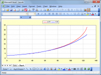
Hopefully any discrepancies produced will not be significant in the frequency range of interest. Note that specifying a full-size Le Cléac'h horn in 4 Pi space then scaling down to 1/4 size, does not give the same profile as specifying a Le Cléac'h horn in 1 Pi space with a 1/4 size throat but similar length to the 4 Pi horn. To illustrate:
100Hz Le Cléac'h horn with T = 0.7 for operation in 4 Pi space:
S1 = 100.00
S2 = 16900.72
L12 = 126.85
Areas divided by 4 for operation in 1 Pi space:
S1/4 = 25.00
S2/4 = 4225.18
100 Hz Le Cléac'h horn with T = 0.7 for operation in 1 Pi space:
S1 = 25.00
S2 = 1961.95
L12 = 126.01
In the first case, S2/4 = 4225.18, quite different to S2 = 1961.95 in the second case.
The attached chart shows the difference in profiles.
Kind regards,
David
Attachments
I have a question regarding a result I am getting when simulating a folded bass bin for a Kappa Pro 12a.
When simulating the same design in 2Pi the roll-off starts way later than simulating in 1Pi conditions. Why is that? I get that the bass should be boosted under such conditions and in relation, the lower mids would be attenuated... But here it just seems like the roll-off starts earlier, with only minimal extension of bass output if any. Where is my failure in understanding?
When simulating the same design in 2Pi the roll-off starts way later than simulating in 1Pi conditions. Why is that? I get that the bass should be boosted under such conditions and in relation, the lower mids would be attenuated... But here it just seems like the roll-off starts earlier, with only minimal extension of bass output if any. Where is my failure in understanding?

Export Rectangular Horn Utility
I'm evaluating a rectangular horn. Are these the correct steps?
I'm evaluating a rectangular horn. Are these the correct steps?
- After simulating on Hornresp I decided on a Tractrix profile with Fc=215Hz, S1=90cm2, S2=1990cm2. This of course assumes an axis-symmetrical shape.
- I'm choosing a width:height ratio of 2:1. Hence a 631mm x 315mm rectangular mouth will basically equate S2.
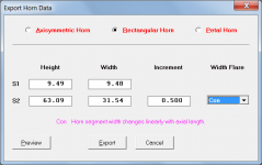
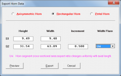
- Then I go to Export Horn Data>Rectangular Horn>set the height & width for S1 (square) and S2 (per the above). But I can't set the width flare to be Tractrix...What should I choose to get an outcome as close as posible to the simulation done on 1)? And how far off should I expect the actual results to be from the simulation?
- Upon exporting, I get a txt file with 7 columns. Some are self-explanatory, but what are these:
- Length: this is the axial length measured from the throat.
- Side length: what is it? It's not the axial length...
- Top length: likewise...what is this?
I have a question regarding a result I am getting when simulating a folded bass bin for a Kappa Pro 12a.
Hi otter17,
Could you please post a copy of the Hornresp Input Parameters window for your design.
Kind regards,
David
Hi LewinskiH01,
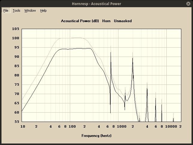
It won't make much difference to the power response which Width Flare setting is used, because the cross-sectional area expansion rates remain unchanged. Choose the option that you prefer, bearing in mind that the Con flare can be used to influence directivity characteristics.
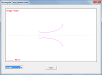
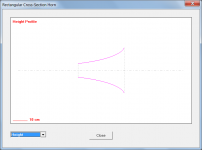
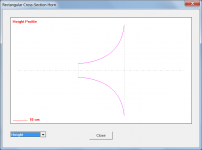
Attachments 1 to 3 use the Uni Width Flare setting.
Attachments 4 to 6 use the Con Width Flare setting.
Attachments 7 to 9 use the Con Width Flare setting but with the S2 Height and Width dimensions reversed.
The Exp Width Flare setting can be used instead, if desired.
The power response results should not be that much different.
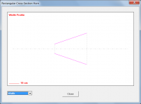
Side Len is length along the curved side panel. To make a side panel out of flexible plywood for example, take a flat plywood sheet and plot the Height/2 values against the Side Len values to get the required profile for the side panel (the Height/2 values need to be plotted above and below the central axis line). When bent to the correct curve shape, the side panel will fit perfectly.
Top Len is the length along the curved top panel, which is the same as the bottom panel. To make a top panel out of flexible plywood, take a flat plywood sheet and plot the Width/2 values against the Top Len values to get the required profile for the top panel (the Width/2 values need to be plotted above and below the central axis line). When bent to the correct curve shape, the top panel will fit perfectly.
Kind regards,
David
Then I go to Export Horn Data>Rectangular Horn>set the height & width for S1 (square) and S2 (per the above). But I can't set the width flare to be Tractrix...What should I choose to get an outcome as close as posible to the simulation done on 1)?
It won't make much difference to the power response which Width Flare setting is used, because the cross-sectional area expansion rates remain unchanged. Choose the option that you prefer, bearing in mind that the Con flare can be used to influence directivity characteristics.
Attachments 1 to 3 use the Uni Width Flare setting.
Attachments 4 to 6 use the Con Width Flare setting.
Attachments 7 to 9 use the Con Width Flare setting but with the S2 Height and Width dimensions reversed.
The Exp Width Flare setting can be used instead, if desired.
And how far off should I expect the actual results to be from the simulation?
The power response results should not be that much different.
Upon exporting, I get a txt file with 7 columns. Some are self-explanatory, but what are these:
- Length: this is the axial length measured from the throat.
- Side length: what is it? It's not the axial length...
- Top length: likewise...what is this
Side Len is length along the curved side panel. To make a side panel out of flexible plywood for example, take a flat plywood sheet and plot the Height/2 values against the Side Len values to get the required profile for the side panel (the Height/2 values need to be plotted above and below the central axis line). When bent to the correct curve shape, the side panel will fit perfectly.
Top Len is the length along the curved top panel, which is the same as the bottom panel. To make a top panel out of flexible plywood, take a flat plywood sheet and plot the Width/2 values against the Top Len values to get the required profile for the top panel (the Width/2 values need to be plotted above and below the central axis line). When bent to the correct curve shape, the top panel will fit perfectly.
Kind regards,
David
Attachments
-
 Attach_8.png39.6 KB · Views: 91
 -
 Attach_7.png30.5 KB · Views: 97
 -
 Attach_6.png39.9 KB · Views: 102
 -
 Attach_5.png40.8 KB · Views: 101
 -
 Attach_4.png30.5 KB · Views: 99
 -
 Attach_3.png39.6 KB · Views: 218
 -
 Attach_2.png40.4 KB · Views: 225
 -
 Attach_1.png30.8 KB · Views: 223
 -
 Attach_9.png40.5 KB · Views: 87
Can I just get some info on a fairly basic question on set-up ?
I'm trying to simulate chopping an existing 120Hz tractrix and adding a 150 or 160Hz tractrix or exponential mouth section from approx half-way .
I just want a multiple segment horn, but can't find the info in the help routine ( so far ) .
I basically need to 'activate' the next row of data ( S2, S3 and L23 ) which is currently greyed-out.
Thanks in advance .....
Thank you!! That was helpful indeed.
Would the acoustical response differ much?
Which option would you choose to achieve my goals?
Attachments 7 to 9 look a lot like Bruce Edgar's rectangular tractrix, doesn't it? Albeit turning it around 90° so the width with conical shape becomes the vertical cross-section.
I should be getting my drivers for this horn tomorrow. I guess next steps should be to get a better estimate of Vtc and Atc, and measure the T/S parameters of the units I receive. Probably more questions coming!
After that I'm hoping to make some trial horns to have a better handle of the correlation between simulation, actual horn, and how it sounds.
Thank you!!
It won't make much difference to the power response which Width Flare setting is used, because the cross-sectional area expansion rates remain unchanged. Choose the option that you prefer, bearing in mind that the Con flare can be used to influence directivity characteristics.
Attachments 1 to 3 use the Uni Width Flare setting.
Attachments 4 to 6 use the Con Width Flare setting.
Attachments 7 to 9 use the Con Width Flare setting but with the S2 Height and Width dimensions reversed.
The Exp Width Flare setting can be used instead, if desired.
Would the acoustical response differ much?
Which option would you choose to achieve my goals?
Attachments 7 to 9 look a lot like Bruce Edgar's rectangular tractrix, doesn't it? Albeit turning it around 90° so the width with conical shape becomes the vertical cross-section.
Very clear. Thank you!Side Len is length along the curved side panel. To make a side panel out of flexible plywood for example, take a flat plywood sheet and plot the Height/2 values against the Side Len values to get the required profile for the side panel (the Height/2 values need to be plotted above and below the central axis line). When bent to the correct curve shape, the side panel will fit perfectly.
Top Len is the length along the curved top panel, which is the same as the bottom panel. To make a top panel out of flexible plywood, take a flat plywood sheet and plot the Width/2 values against the Top Len values to get the required profile for the top panel (the Width/2 values need to be plotted above and below the central axis line). When bent to the correct curve shape, the top panel will fit perfectly.
I should be getting my drivers for this horn tomorrow. I guess next steps should be to get a better estimate of Vtc and Atc, and measure the T/S parameters of the units I receive. Probably more questions coming!
After that I'm hoping to make some trial horns to have a better handle of the correlation between simulation, actual horn, and how it sounds.
Thank you!!
I basically need to 'activate' the next row of data ( S2, S3 and L23 ) which is currently greyed-out.
Hi IslandPink,
Click the Edit button and then double-click on the Tra label. L12 will change from Tra to Con, and the input fields for all four horn segments will be enabled. Note that multiple segment horns can only have Con, Exp or Par flare segments. It is not possible to specify a two-segment horn with a Tra segment and an Exp segment.
Kind regards,
David
Hi LewinskiH01,
When I said that it won't make much difference to the power response, by power response I mean the acoustical power response (as distinct from the acoustical pressure response, which will depend upon the directivity characteristics of the rectangular horn).
That has to be your decision, not mine.
I am not familiar with Bruce's rectangular tractrix horn design, but yes - the constructed horn should be rotated through 90 degrees so that the conical width profile shown in Attachment 8 becomes the height profile of the horn when installed.
Kind regards,
David
Would the acoustical response differ much?
When I said that it won't make much difference to the power response, by power response I mean the acoustical power response (as distinct from the acoustical pressure response, which will depend upon the directivity characteristics of the rectangular horn).
Which option would you choose to achieve my goals?
That has to be your decision, not mine
.Attachments 7 to 9 look a lot like Bruce Edgar's rectangular tractrix, doesn't it? Albeit turning it around 90° so the width with conical shape becomes the vertical cross-section.
I am not familiar with Bruce's rectangular tractrix horn design, but yes - the constructed horn should be rotated through 90 degrees so that the conical width profile shown in Attachment 8 becomes the height profile of the horn when installed.
Kind regards,
David
Could you please post a copy of the Hornresp Input Parameters window for your design.
By way of explanation - I need to be able to simulate the design myself, so that I can check a few things, to be in a position to provide a definitive answer.
Does hornresp use a plane wave model at all times and with all horn types?
Hi AllenB,
Hornresp uses a plane wavefront model in some cases and an isophase wavefront model in others, depending upon the horn system specified.
Kind regards,
David
I received my Faital M5N12-80 and was able to take measurements and use the Hornresp utility to estimate Vtc, which came out to be 110cm3.
David, your estimate of 100cm3 was spot on!!
I am now focusing on measuring the T/S parameters, and on the design of the back chamber.
For a 215Hz fc horn I'm shooting to have an impedance peak around 225Hz, which would be achieved with a Vrc=1.3dm3. For my initial trial I will build a back chamber out of a 6" PVC pipe with fiberglass in it. I have 2" fiberglass panels I would use at the back end of the pipe, and fiberglass felt to line the pipe inner walls.
What should I use for Fr (acoustical lining airflow resistivity)?
What is Hornresp assuming in terms of air volume displaced by the lining, at the given thickness (Tal)?
I guess the back chamber should be equal to the air volume displaced by the driver (0.6dm3) + Vrc (1.3dm3) + air volume displaced by lining + buffer to allow for tunning.
Hi LewinskiH01,
A lucky guess.
For the purposes of the simulation, the actual value chosen is not really that critical.
If the 'Resonances Not Masked' option is selected, specify the lowest value of Fr that removes the resonance spikes present at higher frequencies. (The smaller the value of Lrc, the higher the frequency of the resonances and the less effect they are likely to have on the overall response).
If the 'Resonances Masked' option is selected, it doesn't matter what value of Fr is specified, as it is not used in the calculations.
The value specified for Vrc should include the volume occupied by the lining material but exclude the volume occupied by the driver.
From the Help file: "The rear chamber volume is the effective enclosed air volume behind the driver diaphragm, including any space occupied by acoustical lining material but excluding port tube, driver magnet and chassis assemblies."
For example, a square box with internal dimensions of 10cm x 10cm x 10cm, lined with absorbent material, would have a Vrc value of 1 litre.
Kind regards,
David
David, your estimate of 100cm3 was spot on!!
A lucky guess
.What should I use for Fr (acoustical lining airflow resistivity)?
For the purposes of the simulation, the actual value chosen is not really that critical.
If the 'Resonances Not Masked' option is selected, specify the lowest value of Fr that removes the resonance spikes present at higher frequencies. (The smaller the value of Lrc, the higher the frequency of the resonances and the less effect they are likely to have on the overall response).
If the 'Resonances Masked' option is selected, it doesn't matter what value of Fr is specified, as it is not used in the calculations.
What is Hornresp assuming in terms of air volume displaced by the lining, at the given thickness (Tal)?
I guess the back chamber should be equal to the air volume displaced by the driver (0.6dm3) + Vrc (1.3dm3) + air volume displaced by lining + buffer to allow for tunning.
The value specified for Vrc should include the volume occupied by the lining material but exclude the volume occupied by the driver.
From the Help file: "The rear chamber volume is the effective enclosed air volume behind the driver diaphragm, including any space occupied by acoustical lining material but excluding port tube, driver magnet and chassis assemblies."
For example, a square box with internal dimensions of 10cm x 10cm x 10cm, lined with absorbent material, would have a Vrc value of 1 litre.
Kind regards,
David
- Home
- Loudspeakers
- Subwoofers
- Hornresp