

Ah now the first opamps have considerable gain by virtue of their feedback Rs being 22k. Is there a reason for this?
If this schematic better reflects the 'reality on the ground' then both 4k7s and 22ks are best swapped for 47k. I can't see a point in having gain in the input opamp.
If this schematic better reflects the 'reality on the ground' then both 4k7s and 22ks are best swapped for 47k. I can't see a point in having gain in the input opamp.
Last edited:
Good point - to preserve the same Fc, the input caps (C1,2 in the schematic you posted) should be reduced by a factor of 10, to 100nF.
The ones I intended be swapped were the feedback resistors (R2,3) to preserve unity gain.
Which resistors on your schematic do the 33ks correspond to?
Your analysis seems to me to be correct. The idea behind my suggestion was that harshness comes about from noisy power supplies (in general) and the 4k7s put a load on the power supply of whatever is driving this amp. A heavy load induces harshness in the source component, via its power supplies.
More than happy to oblige")
I did an fresch morning A/B test between Kingrex Tripath and TPA3116D2.
I can´t realey tell them apart in the "Harschness" but Kingrex wins in more air,3D sound with softer middle.
Also tried swapping power supply.
No difference between Kingrex, http://www.kingrex.com/products.php?c=6&s=7,
and the 18.5v/5A Laptop supply, just moore noise in this.
So im not shure if messing with the ground to the decoupler caps help anything?
Oh, sorry, I meant the rectangular polyester black caps, not the round cans. The 1uf cans are simply bias resistors between op-amp stages (to mitigate any DC offset). The two polyester caps are the caps that determine Fc of the LP filter.
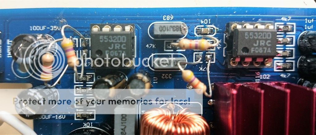
BTW: the two 4k7 resistors that you replace in the photo, one is in the LP filter circuit, the other is a DC bias resistor for the Op-amps.
The graph shows the LP with an Fc currently between 200 and 300 hz. I presume this is post your resistor modifications.
Can you take a photo, much like above, but showing both op-amps and the all 4 resistors you replaced?
Hope you see better here.
Hope you see better here.
And the others are:
C1-C4 is 2.2uF.
C5-C6 is 1uF.
C7 100uF.
C8-C12 1uF.
hi,
i'm also considering to get this 2.1 board with bluetooth function.
i was also curious about the subwoofer channel LP function, i never really knew the exact LPF or what are the sub potentiometer do ?
it seems this board has lots of inconsitency..
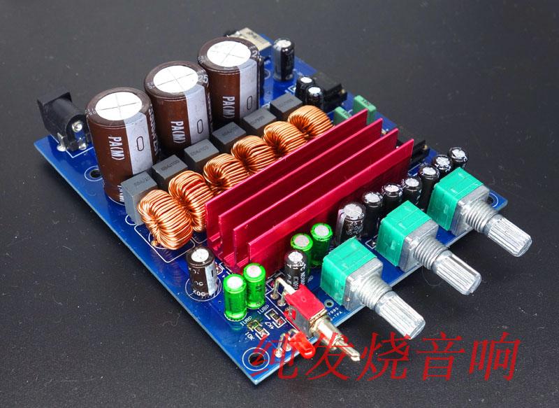
this is supposed to be the newest breeze 2.1 tpa3116, some changes according to them.
1. 3 x3300uf filter capcitor (nichicon 3300uf 25v)
2. upgraded input cap with nichicon muse or elna silmic II ( already another inconsistency )
3.independent bass gain adjustment ?


and here's the schematic i manage to find.. though not really usefull..

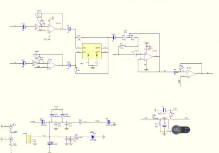

sorry for BWK
i'm also considering to get this 2.1 board with bluetooth function.
i was also curious about the subwoofer channel LP function, i never really knew the exact LPF or what are the sub potentiometer do ?
it seems this board has lots of inconsitency..
this is supposed to be the newest breeze 2.1 tpa3116, some changes according to them.
1. 3 x3300uf filter capcitor (nichicon 3300uf 25v)
2. upgraded input cap with nichicon muse or elna silmic II ( already another inconsistency )
3.independent bass gain adjustment ?
and here's the schematic i manage to find.. though not really usefull..
sorry for BWK
sorry for the radio silence.
No problem, thanks for joining in and the helpful PM as well!
I always drive my amp (with input transformers) from a low impedance source. If you have a potentiometer (volume control) prior to the transformer primary, then the impedance of the source driving the transformer is probably high and varying with volume level. This will cause issues (noise, hum) with many input transformers. You can test this by cutting out the volume control and driving the input transformer directly from a low impedance source (a laptop headphone output would be fine for testing, with volume controlled in the digital domain).
Ahh, yes, I never thought the pot would make much difference, but now that you mention it, I do recall one of the datasheets I read for transformers like this say the assumption is a low impedance source (like 600 ohms). I need the attenuator for volume control though. (Some day I need to make a true preamp so I can put the volume control in a separate device.)
Don't 'short' or leave open any section of the transformer primary. It sounds like you've connected the signal of your unbalanced source to the transformer primary + connection, ground to the CT and then played with having the primary - connection floating or tied to CT. Try connecting the source signal to the transformer primary + connection and source ground to the transformer primary - connection, so the whole primary coil is in series with the source.
That was indeed the original config: RCA+ to transformer primary+, and RCA GND to transformer primary-. That resulted in the hum. I'm now doing that plus additionally jumpering primary- and primary CT. It certainly may be technically "wrong", but it removes the hum.
You're correct that I've never connected the secondary CT to amp input ground, as I was concerned that this would provide a route to ground for the amp input bias voltage. I didn't have any problems with my amp board and transformer with this approach. Remember that the input signals will be connected to amp input ground anyway, as the amp inputs have an impedance to ground.
Yup. I went ahead and connected secondary CT to input ground via a 1uF capacitor. Doing that or leaving it open appears to make no audible difference.
Good luck
You too.
Thanks again, and glad to have you back in the thread.Ah now the first opamps have considerable gain by virtue of their feedback Rs being 22k. Is there a reason for this?
If this schematic better reflects the 'reality on the ground' then both 4k7s and 22ks are best swapped for 47k. I can't see a point in having gain in the input op-amp.
There's no gain on the input op-amps (there's no divider network to ground). The resistors/caps are implementing filters with unity gain.
hi,
i'm also considering to get this 2.1 board with bluetooth function.
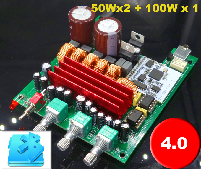
I don't see the Bluetooth circuit in the pic. There is this same board with Bluetooth added on. Another user has had bad experience with this board and the Bluetooth daughter board (lots of squealing, etc.). I'll try to dig up those posts tonight and relay them on.
My experience and analysis has been that the three volume controls are just that: L-R volume, Sub volume and overall volume. Every once in a while I come across a advertisement for this and similar boards that say the sub pot adjusts the sub x-over freq. I believe that those statements are just wrong.
about adjustable freq, i know that is to good to be true..
if i recall, someone here already testing the sub pot, and it only affect the gain at very small amplitude, roll off @ arround 300hz or so..
so, bluetooth board is a no no ?
currently there are 2 different board for bluetooth 2.1
1. breeze
2. JY

i'll also get more info regarding this matter...
thnks
about adjustable freq, i know that is to good to be true..
if i recall, someone here already testing the sub pot, and it only affect the gain at very small amplitude, roll off @ arround 300hz or so..
so, bluetooth board is a no no ?
currently there are 2 different board for bluetooth 2.1
1. breeze
2. JY
i'll also get more info regarding this matter...
thanks
The top pic is the problematic board. This thread from the PE Techtalk forum describes the problem with the top board: two distinct amps, same problem on both. The bottom pic is an alternative similar to one I suggested as it doesn't use the same Bluetooth daughter board. But no info/feedback on that. Not sure if the original poster from this link will report back on the alternative board or if he's given up on bluetooth (see post #5 for the link to an alternative board on eBay ~US$34):
DIY Bluetooth boombox noise issue
Hope you see better here.
Referencing my schematic and amp legend in post 8881 ...
The two modified resistors on the left (R8 & R9) are buffer resistors between op-amp stages and the TPA3116 input on it's PBTL sub channel. I'm guessing that the TPA3116 on these boards is set to 26db gain which, according to TI, makes its input impedance 30K. By increasing the resistor from 4K7 to 47K, you may have reduced the overall gain as the amp input becomes more of a load to the 47K resistor, perhaps not noticeable.
The other modified resistors are the two resistors in the sub's 2nd order Sallen-Key LP filter. Prior to modification, I read two 47K resistors, a 68nf cap and a 33nf cap per the board silk screen. This would put the Fc of your LP filter at 72hz. But it looks like both caps were populated with 68nf caps. That would put the filter's Fc at 48hz.
Now you've replaced the two resistors with the same value (47K) or is the "Orange" color band actually red. That would mean you replaced both 47K resistors with 4K7 resistors. You have two 68nf caps and your filter Fc would become 498hz. And your graph from an earlier post looks like the filter's Fc is ~500hz.
Lastly, it's not a good idea to mod the resistors as you've done. The leads act as little antennas next to the high frequency switch of the digital amp. So if you can put the original SMT resistors back, I would change the LP filter caps (the black rectangular polyester caps) to achieve the cut-off Fc you desire. Using two 33nf caps will put your filter Fc at 98hz with a filter Q of 0.5. This is a Linkwitz-Riley 2nd order LP filter.
Whew ...
Last edited:
Referencing my schematic and amp legend in post 8881 ...
Now you've replaced the two resistors with the same value (47K) or is the "Orange" color band actually red. That would mean you replaced both 47K resistors with 4K7 resistors. You have two 68nf caps and your filter Fc would become 498hz. And your graph from an earlier post looks like the filter's Fc is ~500hz.
Whew ...
Now I dont follow.IT IS 47K nothing else thats in place now.
This amp was an impulse buy and I realized later that the sub channel is
worthless for me with my sub horn who must have steep curve after 80hz
beacause of the high peaks after 100hz.
Then ofcourse you are right, the mods I did was only for the sub channel.
It must be some break in time in the stereo channels that fooled me beacause it sounds better now, not so harsch.
I have an EQ board 24db/octave 80hz wich I will use somehow.
Maybe possible to do an jumper and feed it to the subchannel?
There's no gain on the input op-amps (there's no divider network to ground).
Your bracketed text makes me think that you believe the absence of a divider network means the opamp's acting in unity gain. Well - this is only true for non-inverting configurations, inverting is different.
Inverting Operational Amplifier - The Inverting Op-amp
Now I dont follow.IT IS 47K nothing else thats in place now.
This amp was an impulse buy and I realized later that the sub channel is
worthless for me with my sub horn who must have steep curve after 80hz
beacause of the high peaks after 100hz.
You can change the cutoff frequency of the sub channel to suit your horn. It would need probably only 2 resistor changes. However we have so many apparently different versions of the schematic now its hard to work out which is the correct one.
Your bracketed text makes me think that you believe the absence of a divider network means the opamp's acting in unity gain. Well - this is only true for non-inverting configurations, inverting is different.
Inverting Operational Amplifier - The Inverting Op-amp
You are correct. Sorry, I was just so focused on the sub LP filter which does not have gain. The gain on the audio bandpass is 4.68x.
Last edited:
You can change the cutoff frequency of the sub channel to suit your horn. It would need probably only 2 resistor changes. However we have so many apparently different versions of the schematic now its hard to work out which is the correct one.
The standard approach to this is to leave the resistors and change the caps (of course, you can do it by changing the resistors as you indicate).
Pick two caps from available values to balance two factors: (1) The Fc or cut off frequency; and (2) The Q of the filter.
With the original 47K resistors, and selecting standard value caps: Change C1 to 33nf and C2 to 47nf (top cap in photo). This gives you a Fc of 86hz and a Q of 0.6. This places the 2nd order LP filter squarely between a 2nd order maximally flat Butterworth (Q=0.7) and a 2nd order Linkwitz-Riley filter (Q=0.5).
On my amp I went the other way crossing a 2.1 boombox with an Fc at ~876hz. Pre-modification, my Fc was 107hz. I've modified the amp twice, 1st was at 1073hz needed to go lower. For all three variations (original, 876hz and 1073hz), measurements validated the calculations.
But I'm confused, the original SMT resistors were 47K according to the silkscreen. The new axial resistors are also 47K? Was the board populated with different resistor values than the silkscreen's 47K designations (like the one polyester black cap: silkscreen 33nf, populated 68nf)?
Last edited:
Now I dont follow.IT IS 47K nothing else thats in place now.
This amp was an impulse buy and I realized later that the sub channel is
worthless for me with my sub horn who must have steep curve after 80hz
beacause of the high peaks after 100hz.
Then ofcourse you are right, the mods I did was only for the sub channel.
It must be some break in time in the stereo channels that fooled me beacause it sounds better now, not so harsch.
I have an EQ board 24db/octave 80hz wich I will use somehow.
Maybe possible to do an jumper and feed it to the subchannel?
Some people say the components have to break in (much like a speaker driver). Other's say the listener gets used to the sound. I'm not sure who is correct.
Well, I'd try my cap values for an Fc of 86hz 1st. But to go direct to the sub, you could remove two coupling caps (opens the circuit from the input after the bandpass filter) and tie directly to the sub volume control pins. You could also remove the two caps in the LP filter and that would disable any LP filtering (or keep it and use it as another stage in the overall LP filter scheme.
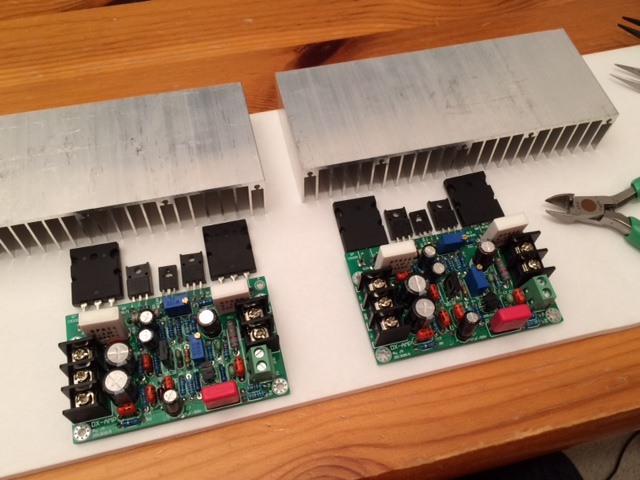
Sorry for the OT post, but just wanted to say I forgot how much fun (and easy) soldering thru-hole components can be compared to SMT's. I just completed a pair of 70w Class AB amps (the DX amp). Finished soldering these from parts in one night. Will setup and test another day. I have heard that these sound really good - we will see I guess.
Attachments

Last edited:
- Home
- Amplifiers
- Class D
- TPA3116D2 Amp