If I am reading your post740 sch correctly it is a series style regulator.
The average current becomes the load that the transformer must satisfy.
add up all the average current demands of the various modules/chips. That becomes the current demand of one rail regulator.
When no Zero Volts/Power Ground current flows all that current passes to the other supply rail.
Thus both supply regulators pass the average demand at the same time.
That then is where you can check the demand on the transformer.
It all changes when there is output current. Some, or all, or in some topologies none of the output current returns via the zero volts line.
Now the two supply regulators do not supply current at the same time.
Fortunately these current to output periods are short as in half cycles and generally of low amps values. The high amps demands tend to be transients and of very short durations.
These do not cause significant heating of the transformer. But they are very significant demands of the decoupling and smoothing capacitors.
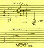
As an exercise:
Draw a circuit of a secondary winding driving a light bulb, nothing else.
Draw the circuit with a bridge rectifier added in so that the bulb sees the current passing in the same direction all the time.
draw the circuit with smoothing capacitor added in beside the light bub.
Now analyse each of those circuits in turn. No software simulators, just pencil and paper.
start with a 12Vac secondary and a 12ohms bulb filament.
When that is all done add an identical second channel consisting of a secondary winding + rectifier + smoothing cap + bulb
then add a link between +ve of one bulb to -ve of the other bulb.
A quick and simple way to put your intuition to the test, is to make a quick and dirty mockup in SPICE and see whether its results fall within 25% of your pencil and paper calculations.
To model a single ended buffer you can use a dual emitter follower in pure class B (no bias spreader at all; bad for crossover distortion but good for simplicity) since you're interested in Large Amplitude Signals, not FirstWatt 0.01% distortion. To model a "bridged amplifier" that drives Speaker+ with one single ended buffer and also drives Speaker- with another single ended buffer in antiphase, you can use two of the above dual emitter followers. IdealOpamp2 models the rest of the guts of the amplifier, plus a resistor from V+ to V- to model the idle current. You can set IdealOpamp2 to swing rail-to-rail with output current limit of 875mA if you wish; that ought to be way more than enough to drive the bases of your MJL3281A/MJL1302A class B buffer. Set IdealOpamp2's bandwidth to 1 MHz or less, guaranteeing that the composite amp+ClassB buffer has >75 degrees of phase margin for unconditional stability. This ain't a hifi product, it's a simulation model. Left channel shown in attachment.
Now instantiate a stereo pair of these (.SUBCKT is your friend), attach realistic loudspeaker loads, drive with Large Amplitude Signals, and monitor the supply current.
Another way to go would be to measure the final hardware itself. Squander GBP 4.00 to purchase a variety of fuse ratings for experimentation, and begin with the highest current one of the lot. Insert a relatively precise (1%) 0.33 ohm resistor in series with the fuse, connect a battery powered 4 digit DVM to measure the voltage across the resistor, and play Large Amplitude Signals into realistic loads. Then use Ohm's Law to extract I=V/R from the measured voltage V and the known resistance R. I recommend choosing a Large Amplitude Signal whose frequency is significantly greater than the fullwave bridge rectifier's charging pulses (100 Hz), so that both power rails are exercised several times within a single sag-down time between charging pulses. I'd suggest at least A-440Hz or better still, 1 kHz. Once you've measured the worst case maximum operating current, you can put that into your spreadsheet along with the worst case maximum inrush current and the other factors you're considering, to help you select a final fuse rating. Remark: it is not impossible to connect N seemingly-identical fuses in series, to give yourself N chances to blow "early". A series string of N fuses also fortuitously provides (N-1) intermediate nodes, where you can attach MOVs, TransZorbs, gas discharge tubes, and other contrivances that you may wish to consider including.
_
Attachments
I and maybe others, have posted that 3times fuse information MANY times in this Forum.
I'm thankful for you taking the time to repeat it again here. I'm new to this and haven't read every post on this forum.
EDIT: I have just investigated Class T fuses. You recommend a fast blow?
I just want to confirm that you indeed meant a fast blow fuse?
The maximum continuous AC output current is 40VA/(15+15)Vac = 1.33Aac
If you feed that through a bridge rectifier and then into a capacitor input filter you will find that the maximum continuous DC current rating is roughly half that AC value, i.e. 667mAdc
A stupid mistake on my part to forget this. Luckily for me I don't think even peak loads will come close to this level.
I'm still digesting the next couple of posts and Mark's also. Will revert.
BTW Mark I had earlier started an LTspice model for the Wire BAL-BAL headphone amp having sourced Spice models for the OPA1632 and the LME49600 which I believe is a close relative to the LME49610 (at least it seemed close enough for my purposes). I got stuck when it came to adding the speaker load, in particular, and input to the amp, took a break and didn't revisit it. Input should be a sine wave at some chosen frequency. I think you are saying I simply have this sinusoidal on each input with them 180 degrees out of phase. I will try this.
(My LTspice auto-generated symbol for the LME9600 isn't sexy looking but should work.)
(My LTspice auto-generated symbol for the LME9600 isn't sexy looking but should work.)
Attachments
Last edited:
Here's a completed version of the Wire BAL-BAL spice modelling. After some schoolboy errors forgetting I had +/- supplies and hence the voltage across the load is twice the amplitude the input signal and some help from the LTspice Yahoo Group I got there. Interestingly the model suggests the amp will oscillate without some compensation around the op amps which Owen has not provided for on the board. Perhaps it isn't necessary in real life.
The only peculiarity remaining in the modelling exercise is that while current flows to/from Vcc and Vee for each individual devices seem to match, when I look the aggregate at the voltage sources there's a very slight mismatch. I'm not going to get too bothered by this however.
I still need to sit back and reflect on this a bit more. I now see that with a balanced/bridged typology how each reg is asked to provide current for both halves of the cycle. Multiply by two for two channels. I still find it a bit confusing when I look at the Vee profile for one of the output buffer ICs and think about it sinking the quiescent and sourcing current on negative halves of the cycle.
Attachments
You can pretend to be the EE professor and ask yourself a series of sanity-check questions
One might expect that the amplifier's "efficiency" is greater than 0% and less than 100%. How much power is drawn from the DC supplies when delivering a full amplitude 1kHz sinewave to the load? How much power is dissipated in the load? What is the ratio of these two powers?
One might expect power-in (from the AC mains) equals power-out (to the load) plus power-wasted (heating up the rectifiers, capacitor ESRs, amplifier transistors). What are these three numbers?
One might expect that since a bridge rectifier contains 4 diodes but a sinewave only has two segments (top_half & bottom_half), there may be times when some diodes are working {dissipating power} and other diodes are resting {dissipating no power}. For each of the four diodes in the bridge, plot instantaneous_power vs time, and calculate the long term average power dissipated in that diode, averaged over 100 milliseconds. Notice that 100ms = 5.0000 cycles of 50Hz and 6.0000 cycles of 60Hz, so it's a good averaging interval for both European mains and for USA mains
I'll try.
At the moment I see that this circuit can still be unstable, even with the 1n compensation, albeit it looks like it is fine for even abusive loads (threshold of pain) from normal headphones. It's certainly not stable for all scenarios that would fit within the swing of the op amp output for +/-12V supply and the 250mA current capability of an LME49610.
And need to shop for fast blow 0.5A fuses...
They may be marked T500mAAnd need to shop for fast blow 0.5A fuses...
Thanks Andrew. Mouser make it easy and have them inventoried under Fast Blow vs Time Delay/Slow Blow.
Are there "rules of thumb" for approximating the primary inductance of a transformer? I don't need a high degree of precision, but it is useful to check things like inrush etc to have a rough estimate. Mark has previously provided a method for measuring actual values, but I was wondering if there's a rough shortcut for plugging in values, for example, for a 40VA transformer when one doesn't yet have the transformer to hand.
Are there "rules of thumb" for approximating the primary inductance of a transformer? I don't need a high degree of precision, but it is useful to check things like inrush etc to have a rough estimate. Mark has previously provided a method for measuring actual values, but I was wondering if there's a rough shortcut for plugging in values, for example, for a 40VA transformer when one doesn't yet have the transformer to hand.
start up does not use the operating inductance.
The first halfwave after power ON saturates the core and the transformer then behaves as a coil without any core.
That is why one sees enormous start up currents and one blows fuses and/or circuit breakers open and/or lights dim.
But luckily for us the transformer only needs a few cycles to establish normal operating core flux and for it to behave as a transformer.
The primary resistance is the main load seen by the mains after the start up pulse has saturated the core.
A 40VA will have a very high primary resistance. It is this resistance that determines whether a soft start would be necessary.
Measure it and work out the predicted current pulse for that resistance.
You might get >200ohms
I have tested quite a few soft starts on different size transformers.
I have found that the added resistance + the primary resistance can be used to predict the AC current pulse. eg. 230Vac 100r of added resistance 4r of primary resistance. Iprimary ~ 230/ (100r+6r) ~ 2.17Aac
I have found that a T rated fuse of around half that value will not blow on many cold start ups.
I would try T1A fuse. That will power a 230Vac 230VA transformer. And may power a 250VA and even a 300VA transformer for loud domestic style listening until the Police come banging at the door !
Last edited:
Ok. I was thinking large VA transformers had significantly larger in-rush than smaller VA transformers - primary and secondary resistances held constant. I see now that halving the primary inductance (and adjusting the secondary inductance accordingly to maintain the correct secondary voltage) in LTspice only has a very minor effect on the first two peaks in the primary waveform with the primary and secondary resistances held constant (which is an impractical assumption). I don't yet have the transformer, but I will measure the resistances when it arrives.
As you may recall, the computer power supply I did has a soft start. For this headphone amp with its smaller capacitance, transformers etc I expect one won't be necessary. I was just looking at simulated in-rush in LTspice and was thinking about the changes needed to the transformer assumptions. Obviously, the first thing that came to mind given the foregoing was the size of inductance.
Thanks.
BTW I was just reading TI's application note SLOA054D on Fully-Differential Amplifiers. Section 11 regarding terminating the input source was particularly interesting. I haven't seen anyone discussing "double termination" of balanced inputs into this "Wire BAL-BAL" amplifier. It seems people just wire the XLR connector directly to the board. The discussion in the TI document including Fig 17 and the example provided (Fig 20) suggest input termination should match the output impedance of the source (in my case, 100 Ohms) with 3 resistors used and, of course, if done so then the values of the two resistors at the input to the amplifier (the TI doc designates these R1 and R3) need to change to maintain unity gain.
Maybe I am missing something. But I guess this is a topic better directed in the thread for the amp. The problem is that thread relating to just those boards isn't particularly active.
Maybe I am missing something. But I guess this is a topic better directed in the thread for the amp. The problem is that thread relating to just those boards isn't particularly active.
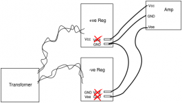
Can I check the correct wiring to operate two of these reg boards as dual supplies +/- 12V?
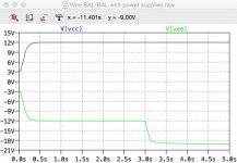
I was planning to configure two boards for 12V operation and connect them as shown in the attached graphic below which I understand to be consistent with Fig 11 here in order to achieve +/- 12V. But maybe I am missing something....because when I try to simulate attaching this supply to my Wire BAL-BAL circuit the Vee voltage level breaks lower when the input signal to the amp turns on. See attached output plots of Vcc and Vee (from the reg boards in the sim). This is with a 3V peak sinusoidal signal input to the amp with a 3 second delay. Doesn't make sense to me.
Also, should all three wires be twisted together as best as possible?
(I've attached the sim but be warned it takes FOREVER to run. Unfortunately I do not understand why. Reducing some more of the time constants might help it run faster but I suspect the issue is more complex. It runs slow as soon as I supply the amp from the reg circuits.
This issue with the supplies - assuming my configuration is correct - plus the instability exhibited in the model while it seems the actual circuit without any op amp compensation has performed well for many people is very much undermining my confidence in this model.)
Attachments
BTW I was just reading TI's application note SLOA054D on Fully-Differential Amplifiers. Section 11 regarding terminating the input source was particularly interesting. I haven't seen anyone discussing "double termination" of balanced inputs into this "Wire BAL-BAL" amplifier. It seems people just wire the XLR connector directly to the board. The discussion in the TI document including Fig 17 and the example provided (Fig 20) suggest input termination should match the output impedance of the source (in my case, 100 Ohms) with 3 resistors used and, of course, if done so then the values of the two resistors at the input to the amplifier (the TI doc designates these R1 and R3) need to change to maintain unity gain.
Maybe I am missing something. But I guess this is a topic better directed in the thread for the amp. The problem is that thread relating to just those boards isn't particularly active.
This document says:
Double termination is typically used in high-speed systems to reduce transmission line reflections and improve signal integrity.
Audio is not a high speed system, termination is not required, but counter-advised because of signal drop and higher distortion.
You need to maintain the close coupled wires for the Flow and Return signals.
That link wire between the two PSU gnds breaks that rule.
Unfortunately that is unavoidable given I am using two existing (+reg) boards. The output connectors on each board can't be changed.
- Status
- This old topic is closed. If you want to reopen this topic, contact a moderator using the "Report Post" button.
- Home
- Amplifiers
- Power Supplies
- Adventures with 5A regulated voltage circuits