Hi,
jauu
Calvin
What does that mean? Connected from where to where?But put a 68nF across the input on top of R3 and R7..
jauu
Calvin
Hi,
What does that mean? Connected from where to where?
jauu
Calvin
Like this:
.
Attachments
Stacked AD844's

Hi George, Look forward to his comments. I suppose if the Buffer is as well matched as the current mirrors then stacking the buffers will probably work.After I talked to Dave More (alias Art Vandelay and very cluey) about the AD844 stacked. he also was impressed with it's sound.
He has been doing has been doing some measurements and progressed with this chip somewhat even more, with using it's buffer also stacked, and getting some very good measurement from it to back up what he's done. I'll get him join this forum to add his details here so others can progress it's great sound even more.
Cheers George
Hi George, Look forward to his comments. I suppose if the Buffer is as well matched as the current mirrors then stacking the buffers will probably work.
He uses a 100ohm resistor on each output before joining them for a single output to counter that problem "if" it's there.
Cheers George
"So it is not weak even if it looks weak"
All else being equal, gains TZ loading etc. Every time I listen to the 844's own buffer...
Not surprised by that at all and why would you think I would be?
George, you should know by now and especially since last ASoN that current drive is something that holds an interest to me and has for some time. But alas, the way you are doing it is great for DIY - but in a broader sense (and commercially) is problematic. I have to find things that works universally and consistent. But for you? Sure, go ahead.
I have a suggestion for you, if this is the route you want to go, then the OPA861 should be tried.
The problem is that the AD844 is current starved, only a few mA. May I suggest that if using this 'trick' is for you, then try by going over to the OPA861 and get four times the current. Then compare that to the result you are getting from using the OTA part only of AD844. Seems it should be tried?
Cheers, Joe
.
Last edited:
As far as the I/V stage of AD844, it's not current starved if it's stacked, I am "shocked" by the dynamic swing I'm getting, and by stacking you kill two birds with one stone as you also lower the input impedance closer to 0ohms current output dacs love to see.
As far as the buffer stage being stacked, I just tried this also with 100ohm isolation in series output resistors then outputs together as Art Vandelay (Dave Moore) said to do, and it's sounds very promising (I'll report latter with the sound advancement) when I've listened for a while.
The beauty of all this, is the whole shebang is direct coupled (not a coupling cap in sight) right through from I/V input to buffer output, as I still have the 20kohm DC offset null trimpot attached to pins 1 and 8 on just one of the AD844's and I'm able to get an stable 0mv!!!! dc offset on the output of the two stacked buffers!!!!!!!
All this in one great 8 pin dip package, a perfect sub for 99% of cdp's out there, and no feedback anywhere, on I/V stage and buffer stage.
Cheers George
Last edited:
........not a coupling cap ....from I/V input to buffer output, as I still have the 20kohm DC offset null trimpot attached to pins 1 and 8 on just one of the AD844's and I'm able to get stable 0mv dc offset on the output of the two stacked buffers..........
Cheers George
Great work George
What do you think of the sound of the AD844 with 2x stacked buffer output compared to using a BUF3?
Can you please try three and then four stacked AD844 buffer outputs now?
I hope Art Vandelay (David) will give a bit more technical info on what I found sound wise below.
Early days yet, but the two stack buffer I believe now is just as "big rich" sounding as the BUF03, (don't miss read "big rich" for fat uncontrolled, they are both very tight and punchy.) Just now I think the two stack buffer has shown the age of the BUF03 as a bit"dirty sounding" and has maybe a bit more insight to fine background detail.
Where the single AD844 buffer didn't seem to have that bigness from memory, it was a little bit anemic/flat.
Cheers George
I hope Art Vandelay (David) will give a bit more technical info on what I found sound wise below.
Cheers George
Hi George,
I'll post some screenshots of the analyser shortly, to verify the improved performance from "stacked buffers" - in addition to the stacked CC sections of the IC.
I found that distortion increases non linearly with the TZ load resistor which suggests that non-linearity of the transcapacitance at the TZ node might at play. Hence I've kept the TZ load resistor at 2k7.
Cheers
David
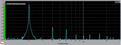
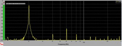
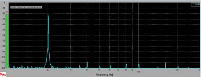
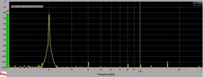
To summarize, performance improvement with 2 buffers is mostly >-10dBfs, as would be expected - ALSO noting that the sound card input impedance is 47k.
Though, I'm not sure to what extent my sound card itself is limiting the measurement accuracy, given that the out of band aliasing products might be introducing some unwanted IMD.
Though, I'm not sure to what extent my sound card itself is limiting the measurement accuracy, given that the out of band aliasing products might be introducing some unwanted IMD.
Last edited:
"I found that distortion increases non linearly with the TZ load resistor which suggests that non-linearity of the transcapacitance at the TZ node might at play"
Could we then conclude that the smaller the tz resistor is the lesser the distortion?
I tried the stacked buffer arrangement a while back(sans the 100 ohm series resistors). From memory, it sounded "shall I say more rounded" than the single buffer. Since then I have taken the signal directly from TZ(1k) onto the input of the amps(250k ohms). When I return home I will like to try Again with the series resistors, but have been happy without additional circuitry.
Could we then conclude that the smaller the tz resistor is the lesser the distortion?
.
Yes, correct.
Re driving the main amps from TZ directly, I haven't tried that myself, mostly because it's a mediocre voltage source, so the voltage gain becomes somewhat dependent on the load impedance, with interconnect cable capacitance etc coming into play.
In some future spare time I might build a dedicated transimpedance input preamp for a very low distortion result.
Here is an alternative to stacking, in fact it may well be equal to stacking up to ten 844s.
George can still take the output from Tz Pin 5.
You also have the option of adding DC nulling as per datasheet. Note you can null both Tz and final output, but there will be some mV difference, so choose one or the other. Also, the 2SK170 current source also affects the DC point.
It can also be used with OPA-660 and OPA-860 - note then the rails need to be +/- 5V.
While the above is a suggested schematic, I have used variations of this in the past.
Cheers, Joe
PS: If anybody builds this and makes necessary adjustment, I can amend this schematic as it loads of my website - I can can update / delete / etc at any time.
.
An externally hosted image should be here but it was not working when we last tested it.
George can still take the output from Tz Pin 5.
You also have the option of adding DC nulling as per datasheet. Note you can null both Tz and final output, but there will be some mV difference, so choose one or the other. Also, the 2SK170 current source also affects the DC point.
It can also be used with OPA-660 and OPA-860 - note then the rails need to be +/- 5V.
While the above is a suggested schematic, I have used variations of this in the past.
Cheers, Joe
PS: If anybody builds this and makes necessary adjustment, I can amend this schematic as it loads of my website - I can can update / delete / etc at any time.
.
Last edited:
I was told by those that have used this "Pedja Rogic"!!!! circuit that an output coupling cap is needed, as the dc offset for them was way out of the nulling's circuit range of adjustability. Not to mention extra noise as well they got on either output.
And the output from TZ is way to high to drive anything external direct, unless a buffer, active or transformer is use.
Cheers George
And the output from TZ is way to high to drive anything external direct, unless a buffer, active or transformer is use.
Cheers George
Last edited:
And the output from TZ is way to high to drive anything external direct, unless a buffer, active or transformer is use.
Please explain?
Re nulling, it is more than adequate, it's just a matter of getting the inputs close to matching - and a number of ways to do that. It is the offset current that causes it. You can even feed current to the "ALT" in my NonStack circuit that equals that of the DAC's.
The above circuit works really well with Burr-Brown current DACs too, the ALT input is also used. Then no problems nulling at all.
Cheers, Joe
.
And the output from TZ is way to high to drive anything external direct, unless a buffer, active or transformer is use.
Cheers George
George if it is too high from Tz it is also too high from a buffer; that has a gain of one isn't it?
Ja
TYPO ALERT!!!!!!!!!!!A little imagination please!!!!
Just about anyone could see I meant output "impedance". Especially talking about having to use a buffer after it ( the TZ)
If you read back a quite a few pages I talked about the TZ output "impedance" at length I think with Abraxalito.
Cheers George
Just about anyone could see I meant output "impedance". Especially talking about having to use a buffer after it ( the TZ)
If you read back a quite a few pages I talked about the TZ output "impedance" at length I think with Abraxalito.
Cheers George
Last edited:
TYPO ALERT!!!!!!!!!!!A little imagination please!!!!
It was only a query.
.
- Home
- Source & Line
- Digital Line Level
- Using the AD844 as an I/V