Thanks. Byrtt or Wesayso pointed out Siri's killer note on TG's site earlier in this thread.
That would be me. I'm possessed with low order crossovers (or none at all as a matter of fact).
")
Are you using the WinPCD (.NET) or the original Jeff Bagby excel spreadsheet (passxodesigner5.1.exe)?
David Ralph's Speaker Pages - WinPCD Release Information
Passive Crossover Designer
Anyhow, please get me the file - either post here or PM me. Thanks.
The second one. I think I got it from here: Jeff Bagby's Software Page
Or maybe it was from the frd consortium
Anyhow, please get me the file - either post here or PM me. Thanks.
File's too large to attach, even zipped and I don't know how to attach in PM
File's too large to attach, even zipped and I don't know how to attach in PM
Just PM'd you.
Which Vifa drivers was Dunlavy using?
I have noticed the presence of the letter "v" in esteemed speaker brands.
Dunlavy, Von Schweichert, Vandersteen - there are probably more...
Is this a trend here? It's like all matresses in the US start with the letter "S" for subliminal message in the illiteration of the first letter for sleep.
Simmons, Serta, Sealy, etc.
I forgot about the other speaker companies with a "v":
Vandermill Audio
http://www.voxativ.com
Last edited:
I'm possessed with low order crossovers (or none at all as a matter of fact).
I'm possessed with both complicated and simplistic approaches
For simplistic approach, I apply it electronically between woofer and midwoofer, so no passive crossover between amp and woofer. JFET active crossover and various active methods have been tried, but not yet DSP based (I used digital only to scan the optimum working area for drivers). When the time comes for me to use miniDSP, I will look into the ADC and DAC sections and might use external board to replace those sections. Or use the programming feature.
For complicated approach, I apply it with midwoofer/midrange. The reason is: Best midrange sound usually comes from relatively bigger diameter midrange drivers, so it will most of the time have issues with HF roll-off. A little "acrobatic" improvisation is needed to get the most out of rigid and lightweight midrange cone.
Last edited:
I forgot about the other speaker companies with a "v":
Vandermill Audio
High End Lautsprecher Made in Germany - Voxativ Loudspeakers
Volti Audio Volti Audio - Hi-Efficiency Horn Speakers
"B" seems popular also, incl some boutique names:
- B&W
- Bose
- Boenicke Audio
- B&O
- Behringer
- Blumenhoffer
- Bastanis
- Blumenstein Audio
- Brines Acoustics
Yes, I would be interested in seeing your design.
Here's what I got. Keep in mind that I only spent a couple of minutes on it just out of curiosity, so I'm sure it can be refined and probably a few of the components could be dropped with more work. But, it's never gonna happen with just a cap and coil.


The resistor in series with the small cap across the big coil is not a real value. It's probably more like 6-12ohms

And here's with a steeper roll off of the RS225 up top.

It cleans up most of the cancellation in the treble.
Now that's a lot notches and crap! But, a lot of parts is unavoidable in a first order passive, See Siri's Killer note. First order xo's aren't simple, they're more complicated. It takes a lot of response shapeing to keep drivers on first order targets, especially a driver like the RS225 with the broad breakup and also when your crossing near fs like you are on the 10f.
Now, first order electrical is certainly simple, but what's the point of that?
The one Byrtt came up for me had a big 57uF cap and a 2.65mH coil. Both were manageable - you have bigger components than that?
No offense to Byrtt, but I think something may be wrong in his model.

This is what happens with 57uf and 2.65mh. There's no avoiding the RS225's natural response.

This is with some level matching with an lpad. I went with a small resistor across the mid to tame the peak near resonance and it doesn't hurt impedance at all.
This actually looks similar to what you were getting with textbook active filters, see the dayton crossing way up high?
Edit: come to think of it, after working with Byrtt's numbers, you could probably delete the series notch on the 10f that is knocking down the fs peak on the low end, then reduce the series resistance inline with the cap from 5 ohms to around 1 and put a small resistor across the mid, probably about 7-8ohms. Might accomplish the same thing with a cheap resistor instead of the huge values in the RLC
There's more than one way to get 1st order rolloffs with parallel passive crossovers.
The old school way is to use a zobel for the LF driver. If the effective Z is flattened, and the woofer's response is dead flat and extended two octaves past the crossover, a textbook choke will work. If the LF driver has a typical rising response type breakup peak, sometimes I'll use something that looks like a 3rd order electrical, but with a damper resistor in series with the shunt cap. These can be tweaked pretty easily to give a nice slope, with fewer parts than an additional RLC trap.
For the HF, a conjugate filter can be used to flatten the Z at Fs, but the large values required means parts get expensive quickly. Alternatively, some sort of aperiodic or TL loading will do the same thing effectively. This is a pain with a tweeter, but easy with a small FR.
Unless the Fs of the FR/HF driver is really low, IME it will still cause problems. For FAST, I find usually a series xover is the only thing that will work, at least without silly parts counts.
Do you mean the lobing caused by the comb interference of the high frequencies that leak out past the woofer to cancel with the full range or tweeter? I have not seen that to be a problem in the measurements yet. The distance between the woofer and tweeter is 8in in my case. Maybe some should be appearing above 500Hz.
Yeah, that's what I mean. However, it's mostly an issue with tweeters, and this is the wrong forum for that...
At 8 inch distance and 500Hz, it's not a big problem. On second thought, that's at about 1/3WL, which is within most guidelines, but likely to have some effect. IIRC some crossover simulators will predict the lobe(s) and angles.
Last edited:
There's more than one way to get 1st order rolloffs with parallel passive crossovers.
The old school way is to use a zobel for the LF driver. If the effective Z is flattened, and the woofer's response is dead flat and extended two octaves past the crossover, a textbook choke will work. If the LF driver has a typical rising response type breakup peak, sometimes I'll use something that looks like a 3rd order electrical, but with a damper resistor in series with the shunt cap. These can be tweaked pretty easily to give a nice slope, with fewer parts than an additional RLC trap.
For the HF, a conjugate filter can be used to flatten the Z at Fs, but the large values required means parts get expensive quickly. Alternatively, some sort of aperiodic or TL loading will do the same thing effectively. This is a pain with a tweeter, but easy with a small FR.
Unless the Fs of the FR/HF driver is really low, IME it will still cause problems. For FAST, I find usually a series xover is the only thing that will work, at least without silly parts counts.
I'm sure there are more ways than one to skin this cat and I'm obviously no expert. I did try a zobel on the woofer and a few other things overall and no, I didn't try a series xo; I only spent a couple of minutes throwing parts at it and didn't want to get into the series xo nightmare. I believe many people are using PLLXO's for this, but I've never done one. In fact, I don't use first order filters and have mostly moved on from full range drivers, so my advice is probably suspect
Like I said, a shunt resistor may be able to be used to partially flatten the impedance peak instead of the conjugate, but by itself that's probably not enough to hit a target BW1.
On the otherhand, I've mentioned an aperiodic/TL a number of times. It could probably kill a few birds with one stone considering the problems he's having hitting shallow slopes this low, but he doesn't want to cut on his box.
If you're using a 3rd order electrical, aren't you introducing the phase shifts in the xo region that he's trying to avoid, regardless of the slope you achieve? And for that matter, a zobel and a damped second order (quasi zobel) act pretty much the same depending on the values.
Anyways, I was really just giving him an idea of the work it might take to hit BW1@350 and showing that a //cap,coil isn't likely to make it happen
Ok, you're right about the zobel! I tried one when I threw that together a few days ago and I don't remember it working well. But, I went back and you can eliminate both notches on the woofer and only keep the elliptical lowpass/notch. Very similar response and phase.
The low end of the mid is still an issue, but a TL is an elegant way to deal with it
The low end of the mid is still an issue, but a TL is an elegant way to deal with it
Here's what I got. Keep in mind that I only spent a couple of minutes on it just out of curiosity, so I'm sure it can be refined and probably a few of the components could be dropped with more work. But, it's never gonna happen with just a cap and coil.
View attachment 485599
View attachment 485600
The resistor in series with the small cap across the big coil is not a real value. It's probably more like 6-12ohms
View attachment 485601
And here's with a steeper roll off of the RS225 up top.
View attachment 485602
It cleans up most of the cancellation in the treble.
Now that's a lot notches and crap! But, a lot of parts is unavoidable in a first order passive, See Siri's Killer note. First order xo's aren't simple, they're more complicated. It takes a lot of response shapeing to keep drivers on first order targets, especially a driver like the RS225 with the broad breakup and also when your crossing near fs like you are on the 10f.
Now, first order electrical is certainly simple, but what's the point of that?
No offense to Byrtt, but I think something may be wrong in his model.
View attachment 485603
This is what happens with 57uf and 2.65mh. There's no avoiding the RS225's natural response.
View attachment 485604
This is with some level matching with an lpad. I went with a small resistor across the mid to tame the peak near resonance and it doesn't hurt impedance at all.
This actually looks similar to what you were getting with textbook active filters, see the dayton crossing way up high?
Edit: come to think of it, after working with Byrtt's numbers, you could probably delete the series notch on the 10f that is knocking down the fs peak on the low end, then reduce the series resistance inline with the cap from 5 ohms to around 1 and put a small resistor across the mid, probably about 7-8ohms. Might accomplish the same thing with a cheap resistor instead of the huge values in the RLC
SATX,
Thanks so much for the XO design. Is there a diagram? I am new to PCD so can't mentally draw the circuit based on populated values.
Regarding the BW1 XO that Byrtt designed, I implemented it as close as I could (I used 5R instead of 4.6R resistors for the padding). Back on post #154 is where I discussed this. Because the mid was not time aligned, it caused an excessive rise at the XO region. When Byrtt added an equivalent of a 3in distance to account for the lack of time alignment, his prediction (using my indoors obtained FRD and XMA files) matched pretty well:
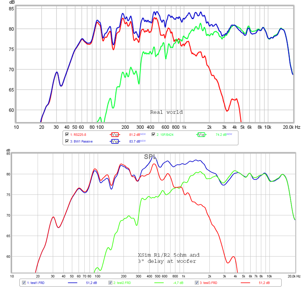
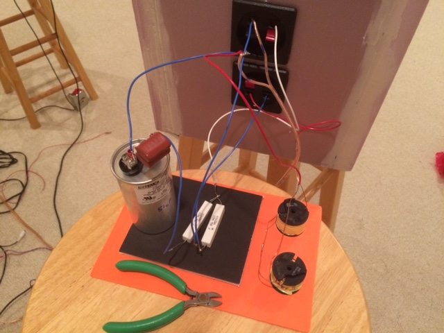
So I think you can get close with "just a coil and cap" plus 2 resistors to pad down the 10F. The photo shows 2 coils used in series to obtain the 2.65mH, and the big motor run cap plus a few film caps to get 57uF. I was able to make this XO for $15 in parts. Although, it does sound like a lot of extra parts will be needed to hit the BW1 textbook slopes via response shaping and RLC conjugate loads, Zobels, etc. We did not do any of that here.
I haven't had anymore time to mess with the passive XO since then though.
Last edited:
SATX,
Thanks so much for the XO design. Is there a diagram? I am new to PCD so can't mentally draw the circuit based on populated values.
Regarding the BW1 XO that Byrtt designed, I implemented it as close as I could (I used 5R instead of 4.6R resistors for the padding). Back on post #154 is where I discussed this. Because the mid was not time aligned, it caused an excessive rise at the XO region. When Byrtt added an equivalent of a 3in distance to account for the lack of time alignment, his prediction (using my indoors obtained FRD and XMA files) matched pretty well:
So I think you can get close with "just a coil and cap" plus 2 resistors to pad down the 10F. The photo shows 2 coils used in series to obtain the 2.65mH, and the big motor run cap plus a few film caps to get 57uF. I was able to make this XO for $15 in parts. Although, it does sound like a lot of extra parts will be needed to hit the BW1 textbook slopes via response shaping and RLC conjugate loads, Zobels, etc. We did not do any of that here.
I haven't had anymore time to mess with the passive XO since then though.
Looks better than expected really, but I thought you wanted to cross really low?
How did you guys deal with the breakup on the dayton? a cap and coil will start the drivers rolling off, but at 6db/octave the breakup will need work. Regardless if you hear the peaking, it causes cancellation in the top octaves.
There's a little cancellation between 4-9k in your measurements, but it doesn't look too bad so I'm guessing you did something here?
As you know the high xo point is a function of the daton's natural response on your baffle and rising Z. Try a zobel as Greg B suggested, it works a treat to roll the driver off more predictably. That being said, I don't think that 2.65 will work, I show the same response as you with that value and it doesn't seem to have anything to do with phase. I needed about 7.0mH to bring it down to 350Hz! Also, if you did nothing to address the peak in the dayton, then try to bypass your coil with a small cap and maybe resistor, around .22uf and 12ohms.
Anyways, regarding my xo, see post #394-396. it had entirely too many parts. I was quickly able to remove 6 components by just adding a zobel and adjusting the values and slightly increasing the size of the main coil. And the series RCL (// to driver) on the mid might be able to be removed with a fairly small shunt resister and an aperiodic loading. The other two RCL's on the mid deal with the areas above the xo, so that would be up to you really to keep or not.
I'll see if I can make a diagram in paint or something or maybe CAD. What do people usually use to make those?
You can make the wire diagram in xsim and it will simulate it for you too.
I did not use anything more than the components listed: 2.65mH coil for woofer and 57uF for mid with a 5R+5R divider to pad the mid down.
Cool thanks! How do you draw lines though. I see xo parts but no wire
- Home
- Loudspeakers
- Full Range
- 10F/8424 & RS225-8 FAST / WAW Ref Monitor