
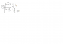
Seems like an awful lot of parts for a FAST!
Not all values are standardized, but the one that probably matters the most is the little cap across the huge coil. The two networks in series with the mid are for response shaping so you could leave them out if you wanted, or meausre/listen and see if it needs it.
Also, the lower end of the 10f isn't as nice with the shunt resistor as it is with the RLC. I'd definitely look into an aperiodic enclosure if I were you even if you stay active. I mean sh!t, you're using foam core for god's sake, how hard could it be.
And polarity's reversed
I didn't really spend much time on this so anyone that knows more about crossovers than me, please feel free make it better
Attachments
Thanks for that. That is a lot of parts - I bet the parts cost more than a miniDSP and two class D amps. Is the 10F same as S1 on top?
Did you try running the XO in xsim? If you did it right, the simulated SR will look like a right triangle.
No I didn't try it. I guess I'd have to import frd and imp and I didn't feel like all that.
10f is on the bottom sorry, I forgot to label it.
Yeah it'd be pricey I'm sure.
I got a pair of RS225S-8's today. I'd like to go the FAST route with them. I have a few small full range drivers. How would W3-871Sc's Tang Band W3-871SC 3" Driver work with them? I also have a pair of W#-879's http://www.parts-express.com/tang-band-w3-879s-3-shielded-driver--264-810I could use.
Any ideas?
I have some other full range drivers if it doesn'tlook like either of these will work.
Thanks,
Mike
Any ideas?
I have some other full range drivers if it doesn'tlook like either of these will work.
Thanks,
Mike
Maybe this one will work.
http://www.parts-express.com/pedocs/specs/264-810-tang-band-specifications-44818.pdf
Thanks,
Mike
http://www.parts-express.com/pedocs/specs/264-810-tang-band-specifications-44818.pdf
Thanks,
Mike
I got a pair of RS225S-8's today. I'd like to go the FAST route with them. I have a few small full range drivers. How would W3-871Sc's Tang Band W3-871SC 3" Driver work with them? I also have a pair of W#-879's http://www.parts-express.com/tang-band-w3-879s-3-shielded-driver--264-810I could use.
Any ideas?
I have some other full range drivers if it doesn'tlook like either of these will work.
Thanks,
Mike
Sure, as long as you like the sound that these drivers produce 400Hz and up. The sensitivity levels are all there and should match well with the RS225, maybe with a tiny bit of padding. There is only 0.5mm xmax on the 871C so it definitely needs a higher order high pass filter. BW2 or LR2 at 350Hz should be sufficient. I would recommend you try a Vifa TC9FD if you have not yet.
Passive XO
satx,
In your passive XO is the two drivers physical offset counted for, and when i set them up in XSim with normal polarity i get such outs and had to reverse one of the drivers, is it meant to be one driver should be reversed") .
.
satx and xrk971,
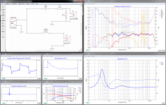
The simple XO that was tried out the coil was not a 2,64mH but a 3,64mH see schematic attached below in picture one including plots. It was a attempt from newbie in passive XO to hit close as possible the miniDSP slopes and as simple as possible because of expensive components. Frd and zma files was from actual measured setup and environment and think if drivers could have been physical aligned the FR plot with blue had been reached when measured in same enviroment, but we sadly ended up the grey plot because of the aprox. 3" woofer is behind 10F. The two resistors xrk971 had was 5ohm instead of 4,5/4,7ohm and change very little.
Learn more and more these discussions and seems the right woofer if seeking perfection to pair a 10F with soft BW1 XO probably must be a less diameter woofer so there be more clean FR/Phase overlap the two between and they can unite more as one driver with transient perfect response.
xrk971,
If you feel the sound was fine enough when acoustic XO point was in the >700Hz area you still can have a listen with 3,64mH/57uF components by putting 10F in a Dagger box beside RS225-8 plus offset them and have a listen this simplistic XO network.
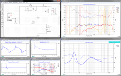
Another simple passive possibility that takes care the 3" offset is below in picture two, 3,64mH needs to be 5,1mH and that one i know you can make in own lab, then a 23,7uF capasitor and 13ohm resistor is needed. The best IR/SR and square waves of these two is the above with physical alligment but this one not bad and still relative simple.
satx,
In your passive XO is the two drivers physical offset counted for, and when i set them up in XSim with normal polarity i get such outs and had to reverse one of the drivers, is it meant to be one driver should be reversed
.satx and xrk971,
The simple XO that was tried out the coil was not a 2,64mH but a 3,64mH see schematic attached below in picture one including plots. It was a attempt from newbie in passive XO to hit close as possible the miniDSP slopes and as simple as possible because of expensive components. Frd and zma files was from actual measured setup and environment and think if drivers could have been physical aligned the FR plot with blue had been reached when measured in same enviroment, but we sadly ended up the grey plot because of the aprox. 3" woofer is behind 10F. The two resistors xrk971 had was 5ohm instead of 4,5/4,7ohm and change very little.
Learn more and more these discussions and seems the right woofer if seeking perfection to pair a 10F with soft BW1 XO probably must be a less diameter woofer so there be more clean FR/Phase overlap the two between and they can unite more as one driver with transient perfect response.
xrk971,
If you feel the sound was fine enough when acoustic XO point was in the >700Hz area you still can have a listen with 3,64mH/57uF components by putting 10F in a Dagger box beside RS225-8 plus offset them and have a listen this simplistic XO network
.Another simple passive possibility that takes care the 3" offset is below in picture two, 3,64mH needs to be 5,1mH and that one i know you can make in own lab, then a 23,7uF capasitor and 13ohm resistor is needed. The best IR/SR and square waves of these two is the above with physical alligment but this one not bad and still relative simple.
Attachments
Great to have you back Byrtt.
I will give separate Dagger 10F a try. If making them separate fixes things that is good to know. The predicted square wave responce looks quite good.
Actually the TG9FD is currently mounted in external Dagger. Maybe give that a try first.
I will give separate Dagger 10F a try. If making them separate fixes things that is good to know. The predicted square wave responce looks quite good.
Actually the TG9FD is currently mounted in external Dagger. Maybe give that a try first.
Last edited:
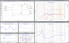
Serial passive XO
Thanks xrk971 and great to have a and welcome salute.
Trying external Dagger box with TG9FD is probably fun, but would expect it has a higher Q roll off at low end and two times 5ohm padding network will probably need new setting.
Below a serial XO filter low in component count, lowers the acoustic XO point compared post 409 and based on same frd zma files. Woofer is set 3" behind 10F in schematic so as FR shows offset is build into component values. Capacitor will be expensive if exotic types are used else one could use a non polar electrolytic or solder two polar ones back to back. Guess its something ala this planet10 requested earlier on in the thread for passive.
tuxedocivic and satx,
Regarding i use frd file measured from actual setup in xrk971 lab room can we say room mode is build into XO filter. That one satx and tuxedocivic is welcome answer, and not because using reference measurement from anechoic enviroment is wrong at all, but can i feel there could be some more precision if XO is tuned to room and then speaker ofcourse stay there in that position . Had looked in some Jeff Bagby spreadsheets and seen room mode how scary it is sometimes just raise height for a driver 10cm to its FR, that's not so much a problem running full ranger but in multi way in the plan where drivers blend gets different FR in different heights, therefore say above because as diy we have the opportunity to tweak that.
Thanks xrk971 and great to have a
and welcome salute.Trying external Dagger box with TG9FD is probably fun, but would expect it has a higher Q roll off at low end and two times 5ohm padding network will probably need new setting.
Below a serial XO filter low in component count, lowers the acoustic XO point compared post 409 and based on same frd zma files. Woofer is set 3" behind 10F in schematic so as FR shows offset is build into component values. Capacitor will be expensive if exotic types are used else one could use a non polar electrolytic or solder two polar ones back to back. Guess its something ala this planet10 requested earlier on in the thread for passive.
tuxedocivic and satx,
Regarding i use frd file measured from actual setup in xrk971 lab room can we say room mode is build into XO filter
. That one satx and tuxedocivic is welcome answer, and not because using reference measurement from anechoic enviroment is wrong at all, but can i feel there could be some more precision if XO is tuned to room and then speaker ofcourse stay there in that position . Had looked in some Jeff Bagby spreadsheets and seen room mode how scary it is sometimes just raise height for a driver 10cm to its FR, that's not so much a problem running full ranger but in multi way in the plan where drivers blend gets different FR in different heights, therefore say above because as diy we have the opportunity to tweak that.Attachments
So for above serial XO I want to physically place the woofer behind the 10F? That is, the full range would be protruding out front of the woofer? Strange looking. I would have to do this with electrolytics. Which polarity should the be placed back to back ? Positive on the outside?
I think that these sound particularly good. Let me know what you think.
Change .asc to .mp3 to listen
Hi X,
I listened to both a few times. I'm not sure what to listen for, but in a comparison, the RC sounded better, probably because it was more varied.
I have 4 of the TC9s. I noticed the sensitivity is a bit lower with the TC9. Would I need to run 2 per speaker to bring the sensitivity up? Or would the BSC kind of balance things out?
Thanks,
Mike
You could run 2 TC9FD's but you get a little vertical lobing. It can sound quite good still as I used to do that with the Nautaloss. It will get you 91dB at 2.83v and that is very good. The single TC9FD is 85dB which is a good match for RS225 which is almost 89dB and after baffle step loss - will match TC9FD.
Last edited:
You could run 2 TC9FD's but you get a little vertical lobing. It can sound quite good still as I used to do that with the Nautaloss. It will get you 91dB at 2.84v and that is very good. The single TC9FD is 85dB which is a good match for RS225 which is almost 89dB and after baffle step loss - will match TC9FD.
Sounds good. So... you would go with the TC9 over the other speakers I mentioned? (I'm pretty sure I know your answer, but just making sure...)
ANother question or two. Are you willing to share the box volume you used and can you describe the dagger?
Thanks again,
Mike
Sounds good. So... you would go with the TC9 over the other speakers I mentioned? (I'm pretty sure I know your answer, but just making sure...)
ANother question or two. Are you willing to share the box volume you used and can you describe the dagger?
Thanks again,
Mike
I think all the info is in post 1 but here it is again:
24 liters for sealed bass box. 1.1 liters for Dagger - but I would make it 1.5 to 2 liters if I redid it to get more bass extension. 3 triangles 6in base x 12in high glued together like tall 3 sided pyramid. Stuff with polyfill or fiberglass and glue onto front baffle where 10F is. Main box was 12in deep x 8in wide x 16in high (all internal dims). Once you subtract Dagger volume you get about 24L. Not a big deal if it is a little off. I add lots of fiberglass stuffing. There is also the option to make the Dagger a vented a periodic TL. Vent the tail out the back with area ratio of 10:1 and progressively stuff the TL thicker and denser.
The 10F is mounted offset from center by 1.5in. center to center from 10F and RS225 is kept below 8in.
Last edited:
I think all the info is in post 1 but here it is again:
24 liters for sealed bass box. 1.1 liters for Dagger - but Inwould make it 1.5 to 2 liters of I redid it to get more bass extension. 3 triangles 6in base x 12in high glued together like tall 3 sided pyramid. Stuff with polyfill or fiberglass and glue onto front baffle where 10F is. Main box was 12in deep x 8in wide x 16in high (all internal dims). Once you subtract Dagger volume you get about 24L. Not a big deal if it is a little off. I add lots of fiberglass stuffing.
Thanks so much for your help. It's guys like you that make this forum such a great place
 . I truly appreciate your willingness to share with those of us who don't grasp the amount of loud-speaker concept you do.
Thanks again,
Mike

So for above serial XO I want to physically place the woofer behind the 10F? That is, the full range would be protruding out front of the woofer? Strange looking. I would have to do this with electrolytics. Which polarity should the be placed back to back ? Positive on the outside?
For physical removable Dagger box use the parallel XO with the values you already have the midrange boost it made should be fair flat when offsetting 10F back relative to RS225. I attach a frd file this parallel XO you can use as target overlay in REW on axis 10F distance 0,5m, and then offset until target is hit then SR should look pretty good or close.
For serial XO there is build in offset for your final box where RS225 acoustic center is behind 10F when measuring on axis 10F distance 0,5m as the frd file had, and in schematic RS225 is set 3" behind therefor cap/coil values are probably asymmetric to count for this and sum fair flat in this serial XO. In that acoustic center can run with frequency there is no guarantee
it hits right because the aprox. 3" (0,22mSec) we had from when acoustic XO point was at 730Hz, this one is acoustic at aprox. 500Hz, but then your measurement FR/SR can point me to tweak values again to hit the right offset for this serial XO. I attach a frd file this serial XO you can use as target overlay in REW on axis 10F distance 0,5m, and if midrange around 500Hz is boosted compared this target there is more distance than 3" and if if 500Hz area have a such out there is less distance than 3" and cap/coil values have to be tweaked.Regarding electrolytics back to back think if they good old axial the metal house is often bonded to negative polar and can have influence for working as a screen or the house can get shorted with other components, watch out for this and choose the most logic, else don't think it matters with modern radial ones where house mostly are floating and therefor doesn't matter if back to back is positive or negative.
There was also a parallel passive XO in post 409 that took care of 3" offset in your final box but it needs other coil value and a cap and resistor added to the components you have already, and lastly it don't throw as good SR and square waves as the two others in sim.
Attachments
satx,
In your passive XO is the two drivers physical offset counted for, and when i set them up in XSim with normal polarity i get such outs and had to reverse one of the drivers, is it meant to be one driver should be reversed
Hey Byrtt, I modeled the physical offset as the woofer 18mm behind the mid. I'm sure this isn't perfect, but is probably in the ballpark. I must be missing something because I don't understand how to RS225 is 3" behind the 10F. Can you explain? You can usually use the xo and slopes to adjust delay so the phase lines up, no need to physically move drivers.
That being said, I know with 1st and sometimes second order, you often need to physically align if you want good phase. The speakers I'm listening to now are LR2 with stepped baffles. In all honesty, I'm a bit confused as to whether the phase should line up or be 45 degrees out with these filters. With phase overlapping you would have a bump @ xo, so....
THe passive I posted shows phase as 40 degrees out and running parallel.
Yes polarity is reversed, I think I said that towards the bottom.
satx and xrk971,
The simple XO that was tried out the coil was not a 2,64mH but a 3,64mH see schematic attached below in picture one including plots. It was a attempt from newbie in passive XO to hit close as possible the miniDSP slopes and as simple as possible because of expensive components. Frd and zma files was from actual measured setup and environment and think if drivers could have been physical aligned the FR plot with blue had been reached when measured in same enviroment, but we sadly ended up the grey plot because of the aprox. 3" woofer is behind 10F. The two resistors xrk971 had was 5ohm instead of 4,5/4,7ohm and change very little.
Learn more and more these discussions and seems the right woofer if seeking perfection to pair a 10F with soft BW1 XO probably must be a less diameter woofer so there be more clean FR/Phase overlap the two between and they can unite more as one driver with transient perfect response.
What does the large cap/resistor bypassing the smaller cap do?
I personally don't think you need a smaller driver. Since you're crossing low, beaming shouldn't be an issue so the only question really is linearity. I said it would have been easier with a different driver, that's all. Something with a smoother extended response may have made life a little easier. As eamples- ScanSpeak P21WO20, Seas U22REX/P-SL, Audax HM210C0, or Scanspeak 22W/8534G00 all have pretty extended, smooth responses with thoughtful baffle layout.
Great to have you back Byrtt.
I will give separate Dagger 10F a try. If making them separate fixes things that is good to know. The predicted square wave responce looks quite good.
Actually the TG9FD is currently mounted in external Dagger. Maybe give that a try first.
X, I'd love to hear more thoughts on the TG9FD, researching that and the SP95 were the whole reason I ended up on this thread
- Home
- Loudspeakers
- Full Range
- 10F/8424 & RS225-8 FAST / WAW Ref Monitor