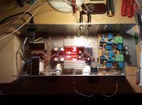
Nice build, by the way - lot's of effort - great to see
Hi Tony, season greets and all that!
I'm playing with the our old mate, the similar dcB1 buffered Xover but with only the high pass filters via the dcB1 and using the UltraPro Berhinger (yes, 'that damn thing'!) for the low pass to get better control of the vagaries associated with 2 different amps, 2 different speakers, etc and is showing great promise so far - might try the Nadja DSP later on to see if the mids/tops is satisfactory, unlike the UltraPro high pass signal (Fx/o is same 125/140Hz)
The crossover is on it's own board so it can be easily swapped out for different frequencies
Are the filter rates (attenuation slopes, frequencies, etc) for the high pass and low pass filters both the same or have you included any compensation for amplifier freq & phase response, driver differences, box diffraction, etc?
Crossover is currently set for experimenting with FAST setups (1st order at bafflestep, which the fullrange forum seems to think is a good starting place). Ordering more parts so I can try a few different points.
Is that block bridge with the 'Red Cap' across it a 'floating ground' mechanism?
It's Rod Elliott's ground loop breaker circuit. There's a resistor in there too.
You generally only need one adjustable volume on either output - suggest you try the high pass filter O/P without the series pot, if the low pass amplifier gain is high enough
That's my plan. The knobs on the preamp are: input select, output select, and volume.
I'm doing a very similar thing with the FR driver taking care of everything about about 140Hz
I get a bit lazy and generally just use a 10R thermistor in the amps and a 100R resistor on signal components for the ground loop breaker - work just fine so far
Ah, that's what that extra switch is for, not a volume control at all ....
Looking good
I get a bit lazy and generally just use a 10R thermistor in the amps and a 100R resistor on signal components for the ground loop breaker - work just fine so far
Ah, that's what that extra switch is for, not a volume control at all ....
Looking good
It's been a long journey, this one, eh!
I've 'sort of' stuffed things up a bit here - I borrowed an 845 valve amp for the last few months and it suits the Coral beta8 drivers so much better than the F5 that it's probably going to be a fixture, or maybe a pending Aikido + F4 type of amp
However, the phase response is do 'out of whack' with the class AB bass driver amp that I'm going to be stuck with using a more complicated filter system for the Xover that can't be done with all pass circuitry, hence the dsp on the bass signal path
It's certainly a better sound from essentially the same speakers but sure is a PIA to organise, plus having to learn how to drive one of these things isn't at all like using one in the studio either (I just ask someone there!) and as the system improves, the anomalies become much more irritating so have to be addressed in turn, so better diffusers are needed and some narrow range bass traps are next - who said this was easy!
Organising components to try 'keantoken's' "Kuartlotron" buffer instead of the dcB1s - I have an idea that they might be more suitable for these filter type circuits - have a look at his website - most interesting things.
Hello,
I'm trying to understand how to realize this XO, I've no electronic background so I ask and write many stupid things...
Let's start with the first one
I have just fill the circuit LR4 that Jacques Merde posts in post 74 with formula to calculate HP and LP; I have also labeled components according to LR2 that JM posts in post 24.
Black, for the original labeling by JM.
Blue, green and red added by me.
Someone could verify it ?
Between LR2 and LR4 there is something different, in LR4 there aren't R9,R10,R15,R16. What are they for ?
Attachments
The sch looks good.
I don't recognise the Low Pass stages where you have tapped off the signal from the input to the Buffer instead of the output. What does this alternative tapping do?
(edit: I should have recognised it, I was reading that thread in 2009 !) & I didn't implement it when I finally built the circuit last year !!!
R7 in the High Pass is probably not required.
Add RF attenuation to the input.
R1 can be made any value from 10k to 220k. Choose to suit what your source needs.
Probably better to go high. Then you can add a parallel resistor to reduce if needed.
Last edited:
as many ways as you want/need
lowest driver+amp gets a Low Pass filter.
highest driver+amp gets a High Pass filter.
All the others get a band pass filter.
this allows a 2way to a 22way, just add more and more band pass filters.
In addition consider band limiting for the whole signal.
RF attenuation at the input gives the highest driver+amp a High Pass filter +RF filter
A high pass filter at the input, or at the active Low Bass stage, can give protection against over-driving the Low Bass driver.
Last edited:
... is it possible to make a 3 ways XO with this design ? how ?
Read Rod Elliot's 24 dB/Octave 2/3-Way Linkwitz-Riley Electronic Crossover article (Project 09) It's a good starting point, you will learn a lot.
Just replace the opamps with the JFET buffer.
Linkwitz-Riley Electronic Crossover
Last edited:
Read Rod Elliot's 24 dB/Octave 2/3-Way Linkwitz-Riley Electronic Crossover article (Project 09) It's a good starting point, you will learn a lot.
Just replace the opamps with the JFET buffer.
Linkwitz-Riley Electronic Crossover
Thank you I'm reading it, there is also a software to calculate R and C values ! very nice !!
I tell you the truth, I don’t understand what you mean for alternative tappingThe sch looks good.
I don't recognise the Low Pass stages where you have tapped off the signal from the input to the Buffer instead of the output. What does this alternative tapping do?
(edit: I should have recognised it, I was reading that thread in 2009 !) & I didn't implement it when I finally built the circuit last year !!!
because the first design of a LR2 from JM has the same low pass stages then the last LR4 he published. But as it looks good, then that's good! Don’t need to understand everything Ok. Can I remove also R6 if I use a gain stage after the XO to match sensibility between speakers ?R7 in the High Pass is probably not required.
Add RF attenuation to the input.
R1 can be made any value from 10k to 220k. Choose to suit what your source needs.
Probably better to go high. Then you can add a parallel resistor to reduce if needed.
If I use a potentiometer, say 100K, before the XO, can I remove R1 ?
as many ways as you want/need
lowest driver+amp gets a Low Pass filter.
highest driver+amp gets a High Pass filter.
All the others get a band pass filter.
this allows a 2way to a 22way, just add more and more band pass filters.
In addition consider band limiting for the whole signal.
RF attenuation at the input gives the highest driver+amp a High Pass filter +RF filter
A high pass filter at the input, or at the active Low Bass stage, can give protection against over-driving the Low Bass driver.
I do not know how to implement RF attenuation but I will see it later when I will try to calculate baffle step compensation and other fine-tuning.
Next step would be PSU...
Rush said :
Finally finished the 2 Hypnotize regulators for the 2 way stereo crossover, had to cut off the B1 part of the boards to save space. I populated the bread board crossover 6 months ago, the Salas Simple phono pre amp and regulators were finished 2 months ago along with the Mesmerize DCB1.
Rush
So… can I use two DCB1 pcb (Hypnotize), one pcb per channel, to power active cross-over without populate the buffer section of DCB1 pcb ?
Or, should I also populate the buffer section of the pcb and use DCB1 buffer before XO ? Is it not redundant ?
Why does Rush use (Mesmerize) DCB1 buffer + DCB1XO ?
Also, looking at the picture of Rodeodave DCB1XO, I see a complete DCB1 buffer running before the XO section….
Attachments
Last edited:
So… can I use two DCB1 pcb (Hypnotize), one pcb per channel, to power active cross-over without populate the buffer section of DCB1 pcb ?
Or, should I also populate the buffer section of the pcb and use DCB1 buffer before XO ?
Yes, two PCB's fully populated, one per channel, but use them as the output HP & LP buffers after the volume control; also make sure the filter buffers are powered from the DCB1's and not another PSU.
Rush said :
So… can I use two DCB1 pcb (Hypnotize), one pcb per channel, to power active cross-over without populate the buffer section of DCB1 pcb ?
Or, should I also populate the buffer section of the pcb and use DCB1 buffer before XO ? Is it not redundant ?
Why does Rush use (Mesmerize) DCB1 buffer + DCB1XO ?
I am using the Mesmerize DCB1 as a preamp buffer and as an input selector. I am also using a pair of Hypnotize boards (one for each channel) to power the crossover. I have a lot of stuff in that box: phono preamp, buffer/input selector, and a two way 24DB/Octave crossover.
I have a 3 outputs per channel, all pass, low pass and high pass.
Rush
If you remove R6, you lose relative adjustability of the inputs to the the drivers.Can I remove also R6 if I use a gain stage after the XO to match sensibility between speakers ?
If instead you have adjustable amplifier attenuations you can remove R6.
To me keeping R6 with it's buffer is the simpler way.
Yes, you can remove that 22k, if you have another DC route for the jFET input.If I use a potentiometer, say 100K, before the XO, can I remove R1 ?
But, why did you choose 22k, if now you are considering 100k that varies down to zero ohms? That seems quite illogical.
And further if you had kept 22k as the Rin of the stage, then that would require an output impedance of the source of less than 4k. You can't get that from a 100k vol pot.
Again defies logic.
More logical would be R1 = 100k or 220k or 1M0
and vol pot = 10k or 20k.
Did you intend only two questions?
Last edited:
Ok, you gave me some good news about PSU I was scared about finding the right PSU.
Here is the set-up I would like to implement, this way it will be simplier for me to understand your suggestions and of course, simplier for you to know what I am talking about:
CD player >> Potentiometer >> DCB1XO LR4>> Gain stage >> My-ref C
CD player output impedance 50ohms.
Potentiometer: (according to AndrewT's suggestion) R1 = 100k or 220k or 1M0 and vol pot = 10k or 20k.
PSU: DCB1 PSU, one pcb for channel.
DCB1XO LR4 as I have posted above.
Gain stage: Which (good) one??? At least 6db of gain to match speakers with different sensibility.
The gain stage would be after XO because JM said that if it is before it causes some distortion. My design is close to what Njepitt did in post 82., but he uses BF862 and I would like to use SK170BL.
Then, baffle step compensation, RF attenuation, notch filter if needed etc...
if I use volume control after the XO, I have better S/N but I need one pot for channel, isn't it? Do I really need DCB1 buffer after DCB1XO ?
Hi Rush,
thank you for replying! Do you use Mesmerize preamp as all pass outputs (bypassing DCB1XO)? I have read that you cut an Hypnotize pcb. You don't use DCB1 buffer as an output after DCB1XO, am I right ?
Do you like as DCB1XO sounds ?
AndrewT, I have read in this thread that you consider a volume attenuation on HP as a "waste", so I was planning to remove it... Maybe I will try to set the gain stage after XO to match speakers and if it is too difficult, I will use R6.
Cheers,
Marco
I was scared about finding the right PSU.Here is the set-up I would like to implement, this way it will be simplier for me to understand your suggestions and of course, simplier for you to know what I am talking about:
CD player >> Potentiometer >> DCB1XO LR4>> Gain stage >> My-ref C
CD player output impedance 50ohms.
Potentiometer: (according to AndrewT's suggestion) R1 = 100k or 220k or 1M0 and vol pot = 10k or 20k.
PSU: DCB1 PSU, one pcb for channel.
DCB1XO LR4 as I have posted above.
Gain stage: Which (good) one??? At least 6db of gain to match speakers with different sensibility.
The gain stage would be after XO because JM said that if it is before it causes some distortion. My design is close to what Njepitt did in post 82., but he uses BF862 and I would like to use SK170BL.
Then, baffle step compensation, RF attenuation, notch filter if needed etc...
HI Itsmee,Yes, two PCB's fully populated, one per channel, but use them as the output HP & LP buffers after the volume control; also make sure the filter buffers are powered from the DCB1's and not another PSU.
if I use volume control after the XO, I have better S/N but I need one pot for channel, isn't it? Do I really need DCB1 buffer after DCB1XO ?
I am using the Mesmerize DCB1 as a preamp buffer and as an input selector. I am also using a pair of Hypnotize boards (one for each channel) to power the crossover. I have a lot of stuff in that box: phono preamp, buffer/input selector, and a two way 24DB/Octave crossover.
I have a 3 outputs per channel, all pass, low pass and high pass.
Rush
Hi Rush,
thank you for replying! Do you use Mesmerize preamp as all pass outputs (bypassing DCB1XO)? I have read that you cut an Hypnotize pcb. You don't use DCB1 buffer as an output after DCB1XO, am I right ?
Do you like as DCB1XO sounds
?If you remove R6, you lose relative adjustability of the inputs to the the drivers.
If instead you have adjustable amplifier attenuations you can remove R6.
To me keeping R6 with it's buffer is the simpler way.Yes, you can remove that 22k, if you have another DC route for the jFET input.
Did you intend only two questions?
AndrewT, I have read in this thread that you consider a volume attenuation on HP as a "waste", so I was planning to remove it... Maybe I will try to set the gain stage after XO to match speakers and if it is too difficult, I will use R6.
Cheers,
Marco
You have either mis-read or mis-understood something...................AndrewT, I have read in this thread that you consider a volume attenuation on HP as a "waste", so I was planning to remove it... Maybe I will try to set the gain stage after XO to match speakers and if it is too difficult, I will use R6............
Relative Treble to Bass sensitivity adjustment must be done somewhere.
You cannot manage without it.
HI Itsmee,
if I use volume control after the XO, I have better S/N but I need one pot for channel, isn't it?
The 22K pots are usually used as matching attenuators for the HF/LF amp & speaker combinations, one of which can usually be omitted.
If you set the gain of the amplifier stage's after the XO, eliminating the need for the presets, then you could use that position for volume controls, and yes it would have better S/N; you would also need a quad pot or two stereo pots which would give you the advantage of L/R balance.
Do I really need DCB1 buffer after DCB1XO ?
If the gain stage is directly after the volume controls (no long interconnect cable), then you could probably omit the output buffer; you would then build the DCB1's as mono and used as the input buffers.
Attachments
You have either mis-read or mis-understood something.
Relative Treble to Bass sensitivity adjustment must be done somewhere.
You cannot manage without it.
Sorry AndrewT, maybe I didn't understant something about that. I will read again this thread to try to understand better... but just be clear: can I adjust treble to bass sensitivity using different gain at HP and LP outputs ?
The 22K pots are usually used as matching attenuators for the HF/LF amp & speaker combinations, one of which can usually be omitted.
If you set the gain of the amplifier stage's after the XO, eliminating the need for the presets, then you could use that position for volume controls, and yes it would have better S/N; you would also need a quad pot or two stereo pots which would give you the advantage of L/R balance.
If the gain stage is directly after the volume controls (no long interconnect cable), then you could probably omit the output buffer; you would then build the DCB1's as mono and used as the input buffers.
Yes, I would like to build a DCB1XO + gain stage in the same box. When we are talking about input and output buffer, are we talking about these parts of the circuit ?
Attachments
each of the circled stages are Buffers..................Yes, I would like to build a DCB1XO + gain stage in the same box. When we are talking about input and output buffer, are we talking about these parts of the circuit ?..........
The left is to ensure the two filter circuits operate with a very low source impedance. A necessary condition for a filter to work as expected.
The two on the right are Buffers to isolate the circuits before them from the outside world.
The upper has an attenuator on the output. That attenuator is not very good at driving cables, so he has added a Buffer.
The lower one is connected to a high impedance node inside the filter. So he has added a Buffer to isolate that high impedance node from the outside world.
Now look at all the other active stages.They are the same. The are all Buffers. Gain is usually very slightly less than 1, maybe 0.99times (~-0.1dB). The gain is NEVER greater than 1times.
- Status
- This old topic is closed. If you want to reopen this topic, contact a moderator using the "Report Post" button.
- Home
- Amplifiers
- Pass Labs
- B1 Active Crossover