Thank you very much AndrewT for your explication of the circuit!
I'm sorry to have so many questions
I try to answer your question about gain stage.
I was looking for a gain stage essentially to match speaker sensitivity (I need about 6db of gain on the woofer) and to avoid pot on the HP. The idea come to my mind reading what Njepett did and what you said about volume attenuator on the HP (edit: but you were talking about amplifier gain and not pre-amplifier gain...)
But... if my amplifier doesn't need a gain stage and I can build something more simple that's even better!
I have two sources:
- CD player output is 2Vrms, 50ohm
- EMU0404 output is 2Vrms, 560 ohm
Amplifiers are My-ref: gain 30, 100k input impedance, 40W(8ohm)
Last edited:
40W into 8r0 is equivalent to 17.9Vac
with a gain of 30times the input to the power amplifier must not exceed 596mVac.
The power amplifier will probably have a voltage divider on it's input. (typically 0.9 to 0.98times)
The input before this voltage divider could be around 660mVac
If your source has a maximum output of 2Vac, then you need ATTENUATION
Not gain !
Because you are filtering the wideband music/audio signal, the separate parts after each filter cannot be more than the wideband signal.
The treble could be around 50% to 90%,
The middle could be around 50% to 100%,
The bass could be around 50% to 100%.
If you were to assume each was the lowest percentage and you wanted to be able to drive your power amps to just reach clipping then you would assume your sources were 1Vac in each case.
You still need attenuation to prevent clipping of your loudest signals.
Last edited:
AndrewT
I asked the same question some time ago in My-ref thread, I didn't get an answer and I wasn't able to calculate it.
Reading your explication, it would be something like this: 40 = 8*I*I and V = 8*I and gain about 30.
So I don't need gain stage, very nice
A little break for you I am reading some information about Hypnotize.
Then I will try to match DCB1XO LR4 + Hypnotize pcb (buffers and PSU) and I will post here schematics.
Cheers,
Marco
I asked the same question some time ago in My-ref thread, I didn't get an answer and I wasn't able to calculate it.
Reading your explication, it would be something like this: 40 = 8*I*I and V = 8*I and gain about 30.
So I don't need gain stage, very nice
A little break for you
I am reading some information about Hypnotize. Then I will try to match DCB1XO LR4 + Hypnotize pcb (buffers and PSU) and I will post here schematics.
Cheers,
Marco
<snip>
Also, looking at the picture of Rodeodave DCB1XO, I see a complete DCB1 buffer running before the XO section….
My xover starts with a shelveing low pass to implement baffle step compensation, and this is what the DCB1 is working into. I think you can see it in one of the schematics i attached. The DCB1 is also powering the whole xover. I think i mentioned current draw and appropriate resistor values somewhere too.
My xover starts with a shelveing low pass to implement baffle step compensation, and this is what the DCB1 is working into. I think you can see it in one of the schematics i attached. The DCB1 is also powering the whole xover. I think i mentioned current draw and appropriate resistor values somewhere too.
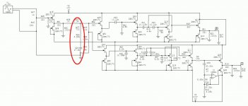
Thank you Rodeodave, me too I need a baffle step compensation. I'm reading what ESP, Linkwitz and P.Joppa say about how to calculate it. P. Joppa use also a cap in parallel to R1 to boost HF...
I have seen your schematic, as you said BSC is R36/37, what U1 is for ?
Attachments
A filter ONLY achieves it's theoretical slope and roll off if the assumptions made in the design hold true.
These assumptions are:
a. The source impedance is zero ohms.
b. The load impedance is infinitely large.
If you add a Buffer, then that Buffer is there to try to attempt to meet those two assumptions.
Now look at your resistors and decide if they are interfering with the "filter" circuit, or are outside the filter circuit, i.e. isolated by the Buffer.
A filter ONLY achieves it's theoretical slope and roll off if the assumptions made in the design hold true.
These assumptions are:
a. The source impedance is zero ohms.
b. The load impedance is infinitely large.
If you add a Buffer, then that Buffer is there to try to attempt to meet those two assumptions.
Now look at your resistors and decide if they are interfering with the "filter" circuit, or are outside the filter circuit, i.e. isolated by the Buffer.
... they are outside the filter circuit. I would say they interact somehow with load impedance of amplifier or with interconnects... or maybe they have some attenuation function, but I don't see any reason to attenuate the output signal...
But they are there also in the orginal B1 buffer
Last edited:
Ok, Nelson Pass says about B1:
"Source needs to have the DC voltage removed by C101 or C201, leaving
the AC output signal, which passes through another safety resistor R104 or
R204.
Resistors R100, R200, R105, R205 are there to prevent the various
potential thumps from switching inputs and turn-on transients."
So R104 is for "safety" and R205 is for there to prevent potential thumps.
"safety" is about what ? Direct current ?
https://www.passdiy.com/pdf/B1 Buffer Preamp.pdf
I post here 3 different design of the cross-over. Could you take a look please ?
First a two-way version with B1 buffer from Hypnotise PCB at the output. Volume attenuator between 10k and 20k, R1=220K. No R8, R14 (gate stoppers) because they are already in the Salas PCB.
Second, the same two ways but with mono buffer from Hypnotise at the input.
The last, is a 3 ways with mono buffer Hypnotise at the input. At page two, I have draw a pass band filter just putting HP and LP in series. Is it ok ?
In all the 3 design PSU is taken from Hypnotise PCB.
I have seen that I can tune electric intensity of the PSU to power the crossover. Is one Salas PSU enough for a mono 3 ways ?
Cheers,
Attachments
Last edited:
the vol pot needs a Buffer.
does the BSC need a Buffer.
What is it's output impedance?
What effect does that impedance have on the XO?
Hello AndrewT, I knew that you answer with a question
From ESP : "It is essential that the compensation circuit be driven from a low impedance source, and the load impedance should be reasonably high. There will be little error with loading above 20k, but basically the higher the impedance, the better. Opamp buffers at the input and output may be used if you cannot ensure that the source impedance is 100 ohms or less, and that the load impedance of the following stage is greater than 20k. My recommendation would be to use a buffer stage at the output with an input impedance of about 100k."
In my case, I'm not sure to have an enough low impedance source, my EMU040 is 560ohm and in the future I will maybe change or add a source with output impedance higher than 100ohm...
On the other hand, Linkwitz uses a shelving high-pass filter directly after the source: source> shelving filter>buffer> XO.
Maybe, in the case of a two way system, if the shelving filter operate on one speaker only, say on the woofer, I can put it just before the power amp and then attenuate the tweeter to match woofer level: source> POT> buffer>XO>buffer>BSC> AMP
The same question is for the position of a low-pass filter to block radio frequency interference...
I have been asked, so I will put it out there -
Is there a common enough design that we can settle on making one or two boards here to power up from dcb1 supply (or any other dual rail), maybe with an option for baffle step correction? I am willing to give it a go if so, assuming there will be some interest over time. I am compelled to see if it can at least come close to Papa's B5 I have in practice.
Let me know.
I have been asked, so I will put it out there -
Is there a common enough design that we can settle on making one or two boards here to power up from dcb1 supply (or any other dual rail), maybe with an option for baffle step correction? I am willing to give it a go if so, assuming there will be some interest over time. I am compelled to see if it can at least come close to Papa's B5 I have in practice.
Let me know.
I would be interested in a pair of 24db two way boards (one if stereo). You could always jumper the unneeded sections if you only wanted 12db crossovers. It would be very handy to have the dcb1 supply on the same boards as the crossover, otherwise they take up a lot of room.
Thanks for asking Tea-Bag,
Rush
Rush, my thinking is to make it as modular as possible. But if one or two larger boards can cover everything, that would be great. But someone will have to bless such as circuit. Jumpering between different db crossovers is smarter and less expensive than creating nine different boards
I have always been a 12db main myself, so I submit a vote for that.
I still dont understand how close the circuit is to being standardized. I will need to look further or someone bluntly explain it.
I have always been a 12db main myself, so I submit a vote for that.
I still dont understand how close the circuit is to being standardized. I will need to look further or someone bluntly explain it.
- Status
- This old topic is closed. If you want to reopen this topic, contact a moderator using the "Report Post" button.
- Home
- Amplifiers
- Pass Labs
- B1 Active Crossover