But if your circuit is class A (and I think that any preamp with pretension to quality is class A), then how does it matter?.
Class A and open loop, probably it doesn't. But add a global feedback loop, and the PS output impedance could make the difference from stability to instability.
To better understand, recall that frequency compensation is usually referred either to ground or to the supply lines. Having a large output impedance, the power supply will add a zero to the loop gain. In fact, the simplest shunt compensation will become a lead-lag compensation.
This zero may throw your carefully designed amp into instabilities. Of course, this is not necessary true for audio, since almost any half-decent design will sound great in the ears of the beholder (and the review chimps, if your name is JC).
Raw supplies do have horrible line regulation, but for 20mA from 1000u it will take about 100mS (two missing mains periods) to drop the same amount of 1.5V that would drop under load. Very unlikely to happen, and as for slow mains variations those could also be ignored, since they may have no other effect that some early clipping, who cares?
There is no MKT capacitors in Wima range. Their code for polyester capacitors is MKS, for metalized PP MKP. Which brand of 220nf PP do you use for electrolytic decoupling? MKS-4 is a polyester dielectric cap(I saw it in your headphone amp power supply.There are basically two series of caps from Wima, MKT used for power filtering and MKS used for signals, and both have additional subcategories. While similar in frmat and base material, they are not the same.
I use MKT for power line filtering and MKS for signals, just as suggested by the manufacturer. Beside Wima, I might also use Siemens caps, and on occasion, Plessey caps.
I have been using Wima and Siemens from my first project in 1975, so we are old friends. Looking into somewhat older literature from the manufactuers, you will find that for example Kensonic Accuphase also uses the very same combination and in fact advertises it.
Inside the same series, they vary in voltages, size and even base material, so when buying make sure you have checked and rechecked.
Regarding tantalum, for smaller values, say 1 ... 47 uF, I have yet to see a better decoupling capacitor by anyone. Their problem is relatively low voltages at which they work, which is obvious to everyone. Less obvious is that the small drop types are not very reliable and can play tricks with you. However, they are relatively cheap. Much better quality will cost more and is available in block form from some reputable sources, such as say Roe(derstein). Good for zener diode filtering and things like that, not good at all for signals, I tried on several occasions and didn't like what I heard, bypassed or not.
"To have ultra clean power supply with highish Zou to me seems nonsense. Stuart remarked earlier that this should be sorted out by the subsequent circuit, but if that is so, why have an ultraclean PSU in the first place?"
A low z out will mean any noise in the PSU is coming from a low z and it's therefore harder to filter and decouple out. Then you have trace inductances to deal with, and less than ideal decoupling caps. Take a good reg and add these parasitics in and suddenly overall system performance is not grand.
Treat the (reg) and the (amplifying stages) as a system.
For reg testing, I use fast rise fall times for load and line perturbations, and all decoupling caps and reg + amp stages include parasitics.
Last edited:
Treat the (reg) and the (amplifying stages) as a system.
This x1000.
This MKT/MKS comparison of capacitors for bypass purposes is a plain nonsense.
Who compare MKT/MKS, they are both polyester dielectric capacitors.MKS is Wima code. But I wish to know why some high end manufacturers use polypropilene both film and foil and MKP on power supply rails.One example is Parasound JC-3 phono preamp with big REL-caps in PS decoupling. I am amateur, but many experts , including people from Wima are against using PP capacitors in power supply.
They produce broad range of PP caps and they know their products and application well.
Too many contradictions and different opinions in designing PS for audio.
Kamis, If you're measuring PSU noise and impedance, the very best MKP will be no more than 1% better than a cheap MKT. The ESR and DF figures of film caps only matter when the cap itself is under such a load that it dissipates heat (several amps to hundred of amps). Then it has to have low enough loss that it doesn't melt itself. But the DF and ESR only account for less than 1% of the capacitor's actual impedance and ability to filter signals, usually far less than even that.
RNMarsh, opamps don't have as good PSRR at RF, and they can act up if there are supply transients. They don't however have the enormous noise and output inductance of chipregs. So there is probably a place for them in PSUs.
RNMarsh, opamps don't have as good PSRR at RF, and they can act up if there are supply transients. They don't however have the enormous noise and output inductance of chipregs. So there is probably a place for them in PSUs.
But I wish to know why some high end manufacturers use polypropilene both film and foil and MKP on power supply rails.
One example is Parasound JC-3 phono preamp with big REL-caps in PS decoupling.
I am amateur, but many experts , including people from Wima are against using PP capacitors in power supply.
Well designed PP capacitors have low loss and low inductance. When connected to inductive components (or long wires or traces),
a resonant LC circuit is formed, which can ring and have undesired impedance behavior. Often a parasitic or physical R can be used
to damp this resonance. In this sense, quality PP capacitors can be "too good" for certain uses.
Why not something a bit different and original for a change?
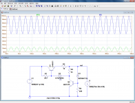
We always see the same old rehashed shunt regs fed by a CCS, but if they work in tandem instead of independently, it brings many benefits: reduced dissipation, better rejection, lower output impedance.
I tested the concept with this circuit: the shunt reg formed by D1 and Q1 works at ~10mA, and the CCS is servoed to keep this current constant.
Here, the sim shows the behavior with combined rippled input and an output current varying between 50mA and 150mA.
Performance looks interesting, even without any optimization or additional bypass caps
It has probably already been invented twice (at least) anyway....
Elvee
If you have servoed the CCS to keep the shunt at 10mA - you have
effectively a/ turned the shunt into a lowish z CCS b/ turned the top CCS
into a series pass reg.
So the traditional shunt advantages of localised current loops and no AC
current back into the PS are lost.
10 points for lateral thinking though
")
T
Kamis, If you're measuring PSU noise and impedance, the very best MKP will be no more than 1% better than a cheap MKT. The ESR and DF figures of film caps only matter when the cap itself is under such a load that it dissipates heat (several amps to hundred of amps). Then it has to have low enough loss that it doesn't melt itself. But the DF and ESR only account for less than 1% of the capacitor's actual impedance and ability to filter signals, usually far less than even that.
RNMarsh, opamps don't have as good PSRR at RF, and they can act up if there are supply transients. They don't however have the enormous noise and output inductance of chipregs. So there is probably a place for them in PSUs.
The advantage of MKS over MKP is much smaller form factor = lower ESL
Example: MKP / 1uF / 100V = 22.5mm lead spacing versus 5mm for MKS
The lowest ESL films are SMT acrylic dielectric, but still not approaching
MLCC.
The other issue that doesn't appear to be often recognized here is that
these caps all sound subtly different when used as PS bypass. parallel with
electros and it's a field day. Choose your poison
T
Hi,
IOW, horses for courses. I see so many so called high-end companies using MKP caps in their PSUs that it makes me wonder. Did they forget about the usefulness of an electrolytyc's ESR or is this just a hey, we use the best possible parts, so buy me thing and listen to the unfiltered hash?
Cheers,
Well designed PP capacitors have low loss and low inductance. When connected to inductive components (or long wires or traces),
a resonant LC circuit is formed, which can ring and have undesired impedance behavior. Often a parasitic or physical R can be used
to damp this resonance. In this sense, quality PP capacitors can be "too good" for certain uses.
IOW, horses for courses. I see so many so called high-end companies using MKP caps in their PSUs that it makes me wonder. Did they forget about the usefulness of an electrolytyc's ESR or is this just a hey, we use the best possible parts, so buy me thing and listen to the unfiltered hash?
Cheers,
Did they forget about the usefulness of an electrolytyc's ESR or is this just a hey, we use the best possible parts, so buy me thing and listen to the unfiltered hash?
Electrolytics have a bad reputation among some circles in high end equipment, like Conrad Johnson, for example. The ESR does tend to increase with age.
...
Too many contradictions and different opinions in designing PS for audio.
And you have answered your own question. Some people like the priest, others prefer his wife (Neko voli popa, a neko popadiju).
People tend to use what they have good experince with rather than obeying the text books word for word.
Last edited:
Elvee
If you have servoed the CCS to keep the shunt at 10mA - you have
effectively a/ turned the shunt into a lowish z CCS
That isn't the case: the shunt reg continues its shunt-regging duty, but it sees a much lighter burden.
However, should the link between the two regs be severed, it would see the full variation again.
The shunt reg steers the whole composite: it continues to work for itself, and it also drives the slave CCS.
The shunt action is thus a feedforward path in the overall regulation picture
More or less, but it has to be qualifiedb/ turned the top CCS
into a series pass reg.
That is indeed the case.So the traditional shunt advantages of localised current loops and no AC
current back into the PS are lost.
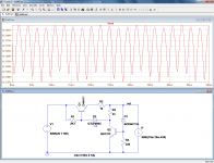
Here is a simplified, more "didactic" version, with less components and less gain, making the inner workings more visible.
First, the current ratio is more reasonable: the shunt reg draws up to 25mA (no load condition), and the maximum output current is 100mA; the ratio is thus 1:4.
From the currents in the load and the shunt reg, it is obvious that it still operates as such, it is just helped by the modulation of the CCS.
Drawn this way, it is obvious that the CCS is actually that, it has simply been made adaptative.
BTW, even this oversimplified version doesn't work badly, see second pic.
Attachments
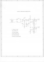
Slightly improved power supply from about 35 years ago.
That looks funny. Is that buffer just faithfully replicating the input ripple to its output??
jan
That 'buffer' is a 3 pin adj regulator..LM317.That looks funny. Is that buffer just faithfully replicating the input ripple to its output??
jan
Dan.
Slightly, indeed: you don't provide any isolation from AC, ground side.Slightly improved power supply from about 35 years ago.
I don't want to be desagreable, but, when you don't answer to questions about this, what the interest to multiply cap multipliers, when one can bring more benefits if connected ground side instead of active rail one ?
And you have answered your own question. Some people like the priest, others prefer his wife (Neko voli popa, a neko popadiju).
People tend to use what they have good experince with rather than obeying the text books word for word.[/QUOTE
But some objective rules should be followed.
But some objective rules should be followed.
Certainly, but whose objective rules? My point is, somebody makes a good power supply and that becomes his objective rule, because it objectively works very well. And that can be verified by measurements.
However, as several people here pointed out, each and every circuit is essentially a set of compromises. The question is: what are your primary goals when making a PSU? I joked with Richard about it, but his question is very pertinent.
Speaking strictly for myself, my prime goal is as little noise as I can squeeze out of it. One can, as someone pointed out, go for minimum output Z, but then you compromise on noise. In my case, that would mean turning that single transistor into a Darlington one; I tried that several times and was not very happy with that.
Of course, someone else might feel differently. It all depends on who you ask.
- Status
- Not open for further replies.
- Home
- Member Areas
- The Lounge
- John Curl's Blowtorch preamplifier part II