These drawings you are doing are wonderful, xrk. Thank youMakes my job with CAD a lot easier.
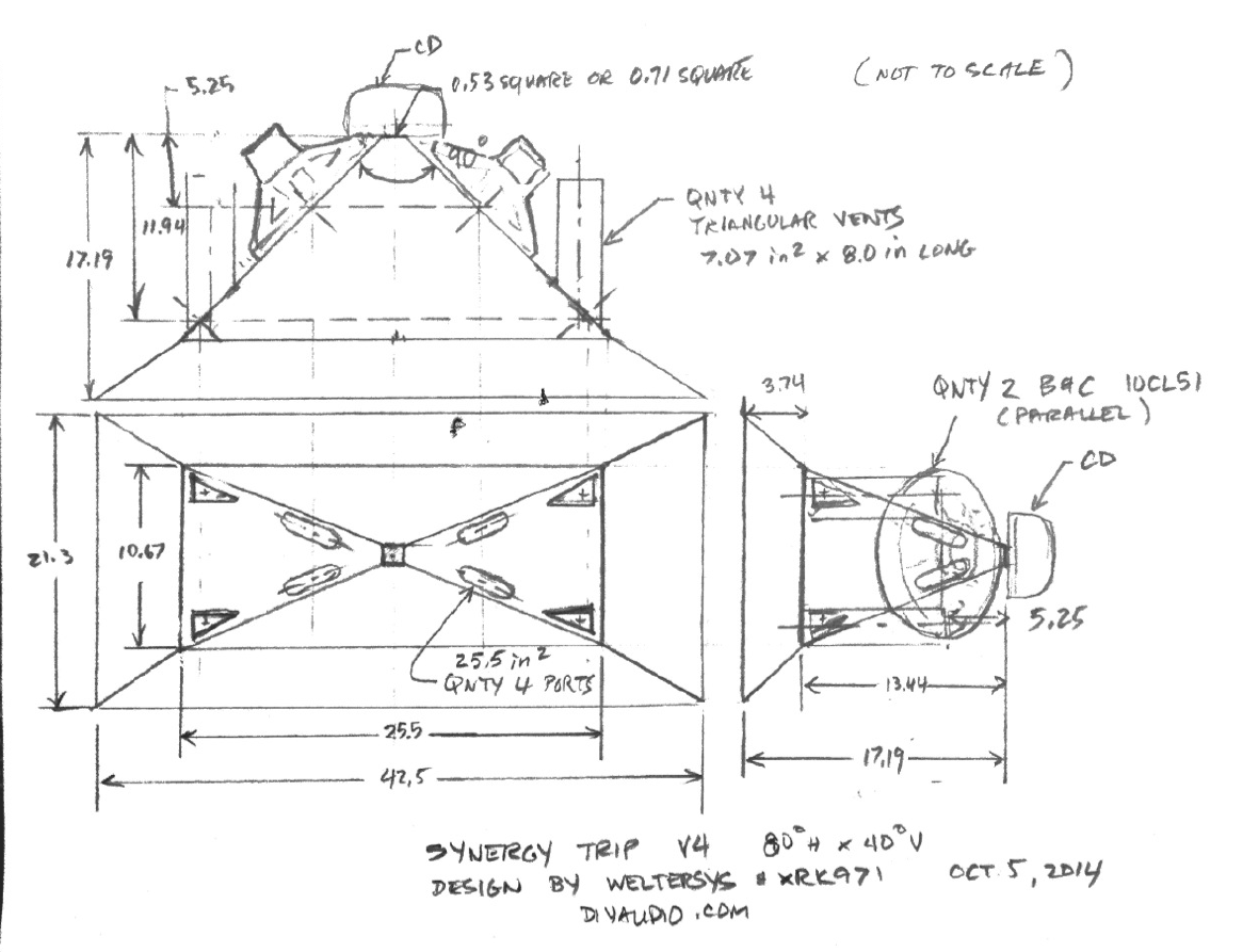
Also I really like the way the triangle ports look. They make this thing look like it means business! Do you think the dual 10" driver version will be enough to match the sub?
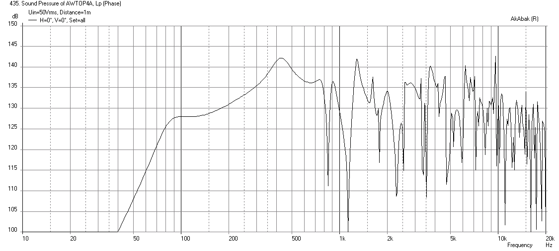
You are welcome. Your CAD drawings are what makes it nice and easy for us to cut and build though - appreciate your speedy work on this. Car troubles? Usually Toyota trucks run forever - I had 1983 long bed that had 220k and still strong until a 16 yr old jacked it up from the rear and totaled it. No worries we gotta eat, and we gotta drive, especially in LA. The dual 10CL51 design can reach 127dB peaks - you may want triple driver version as your 2ohm amps can handle it. Here is the peak SPL from the two driver sim - even tuning up to 100Hz won't get you the SPL you need.
Let me run you a sim without the extension and 3 drivers to see if you hit 130dB.
Last edited:
Hi xrk971,
This may be another stupid question, but how are you going to position the third driver, and still maintain a balanced injection? Also, @ Xmax you'll have at least a few dB of loss over the simulation.
Maybe instead of getting the most bass extension from the synergy horn it would be easier to extend the upper response of the TH?
As to the ports, how about using ports as you might find them in a compound/Onken speaker(see attached)? I remember an old Frazier 8" back-loaded horn, that distributed the horn output all the way around the forward outside edge of the speaker.
Regards,
Attachments


but how are you going to position the third driver, and still maintain a balanced injection?
I don't know if it matters much that the injection ports only come from the top wall for the middle driver. If there are any asymmetries at least it is balanced left.right
Maybe instead of getting the most bass extension from the synergy horn it would be easier to extend the upper response of the TH?
Problem is, JG already built the sub and it won't go above 100Hz IIRC.
As to the ports, how about using ports as you might find them in a compound/Onken speaker(see attached)? I remember an old Frazier 8" back-loaded horn, that distributed the horn output all the way around the forward outside edge of the speaker.
This certainly can be done but may grow box and complexity of build. Personally, I am lazy and would do the qnty 8 x 2in dia x 5.5in long SCH 40 PVC ducts near the corners of the horn mouth and be done with it...
Here is the sim with the 8 BR ports as described above:
Last edited:
Hi xrk971,
Post #426: "...JG already built the sub and it won't go above 100Hz..."
1/4 wave resonators as in the DTS-20 could be added to equalize the two main peaks, that should not only improve the SPL, but also the phase. Seems that is too much of a complication for most to consider. In the case of JG's TH it could even be added in the general mouth area. (I'll attach one of my favorite pictures.)
Just using the distributed ports left and right would probably not be too difficult, but tuning may be more difficult. Looks like y'all got it all under control anyway.
Regards,
Attachments

Good idea about Helmholtz resonators to trim those peaks. They sure sim well when I have added them in the past. For 100Hz peak you would need something like 4ft long one maybe 4in PVC pipe? Is the DTS using the resonators connected to the compression chamber side and coming through the baffle and extending into main mouth cavity with sealed end?
Hi xrk971,
The tubes in Post #427 are not Helmholtz resonators, they are 1/4 wave long, sealed on one end stubs. A light filling w/ fiberfill will broaden the effect. You can add them as closed end ducts of 1/4 wave length to any node of your AkAbak simulations. in the TH they would connect at the S2 side. My guess would be that 1-1/2" to 3"Dia. PVC pipe would work just fine.
Regards,
Last edited:
Hi Y'all,
Just a few references of interest:
http://www.diyaudio.com/forums/subwoofers/114340-tapped-horn-dummies-11.html#post1598351 - Post #104
http://www.diyaudio.com/forums/subwoofers/114340-tapped-horn-dummies-13.html#post1600513 - Post #128
http://www.diyaudio.com/forums/subw...tive-tapped-horn-project-361.html#post2464063 - Post #3602
Gotta run.
Regards,
Hi xrk971,
The tubes in Post #427 are not Helmholtz resonators, they are 1/4 wave long, sealed on one end stubs. A light filling w/ fiberfill will broaden the effect. You can add them as closed end ducts of 1/4 wave length to any node of your AkAbak simulations. in the TH they would connect at the S2 side. My guess would be that 1-1/2" to 3"Dia. PVC pipe would work just fine.
Regards,
I thought Helmholtz resonators could be 1/4 wave tubes? Anyhow I will gin something up as it seems JG looks to be interested.
I thought Helmholtz resonators could be 1/4 wave tubes? .
Doesn't really matter what you call it, it still works the same. FWIW I call them 1/4 wave traps or stubs. Anyway, the fact that it's long and skinny and the length is determined by the frequency you want to eliminate means it's working with 1/4 wave resonance, not helmholtz.
What is involved with these resonators, am I understanding correctly that a hole is cut out of S2 and the pipe extends the opposite way into S3/S4?
Cut a hole out of S2 (or really anywhere along the flare path you would like to have it, assuming it sims well) and then run the tube out the back. You don't want this thing inside your horn flare. Each 1/4 wave trap will suck out a single frequency (or small band of frequencies) based on it's 1/4 wave length. In the dts-20 pic that was posted there are two stubs so it's sucking out two response peaks in that design.
Jgirl TH - Mad Max Edition
JG,
I think you will like this...
Basically, go to HD and buy some qnty 4 x 3in SCH 40 PVC elbows, end caps, and 20 ft of SCH 40 3 in PVC pipe. Also get some fiberglass or rock wool if you don't already have it. Drill some holes (as big as possible close to 3 in) on the side walls near S2 (in the compression chamber area). If you can get access to the actual baffle board, even better, then run those out through the sides. I envision this box to have 4 stacks coming up like a nitro fuel car dragster engine out of Mad Max - except that the "exhaust" stacks are capped off. (more practical approach is to turn the tubes into handles for transport...)
You need 2 sets of pipes:
qnty 2 x 37.7in long (including elbow and end cap)
qnty 2 x 26.1in long (including elbow and end cap)
mount them with the open end somewhere near S2, stuff them with fiberglass or rockwool progressively so that it is looser towards the open end going to more and more dense towards the end cap. You will need to experiment so don't glue the end caps on yet.
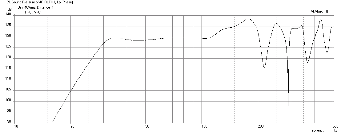
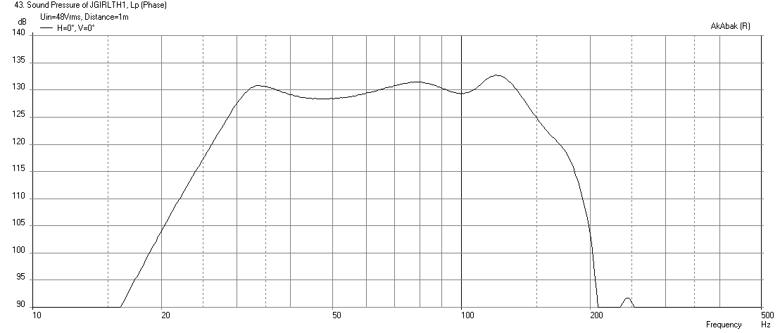
Here is your TH sim in its current state driven to xmax with no low pass filter:
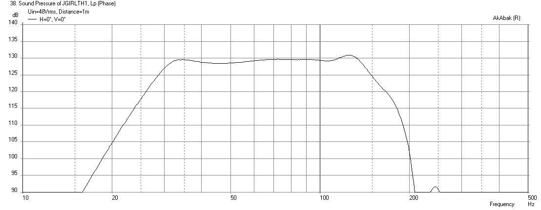
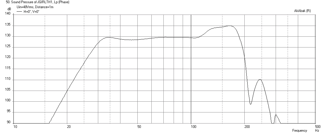
Here is what your TH in its current state looks like with a -48dB/oct LPF at 130Hz applied:
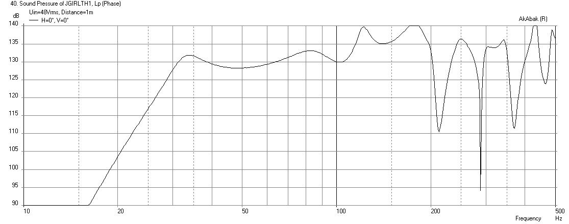
Here is what it looks like with the above stub tubes installed (no LPF) - note that in addition to the peaks at 122Hz and 176Hz being tamed, the sag at 50Hz is almost eliminated:
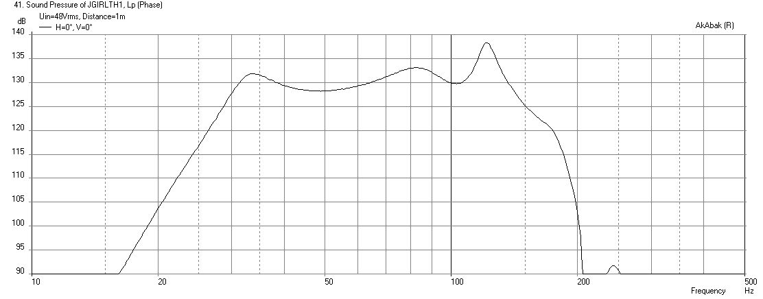
Here it is with the 130Hz LPF applied - pretty good upper extension and flatter response throughout - it becomes a better speaker, flatter response, can go up yo a higher XO point:
If you could only do one set of tubes, pick the 26.1in long ones and here is the response with LPF applied:
If you wanted to XO higher say at 170Hz, still doable, just need a -5dB high shelf applied in miniDSP vs a peak cut filter:
You are too good to me, xrk
What is involved with these resonators, am I understanding correctly that a hole is cut out of S2 and the pipe extends the opposite way into S3/S4?
JG,
I think you will like this...
Basically, go to HD and buy some qnty 4 x 3in SCH 40 PVC elbows, end caps, and 20 ft of SCH 40 3 in PVC pipe. Also get some fiberglass or rock wool if you don't already have it. Drill some holes (as big as possible close to 3 in) on the side walls near S2 (in the compression chamber area). If you can get access to the actual baffle board, even better, then run those out through the sides. I envision this box to have 4 stacks coming up like a nitro fuel car dragster engine out of Mad Max - except that the "exhaust" stacks are capped off. (more practical approach is to turn the tubes into handles for transport...)
You need 2 sets of pipes:
qnty 2 x 37.7in long (including elbow and end cap)
qnty 2 x 26.1in long (including elbow and end cap)
mount them with the open end somewhere near S2, stuff them with fiberglass or rockwool progressively so that it is looser towards the open end going to more and more dense towards the end cap. You will need to experiment so don't glue the end caps on yet.
Here is your TH sim in its current state driven to xmax with no low pass filter:
Here is what your TH in its current state looks like with a -48dB/oct LPF at 130Hz applied:
Here is what it looks like with the above stub tubes installed (no LPF) - note that in addition to the peaks at 122Hz and 176Hz being tamed, the sag at 50Hz is almost eliminated:
Here it is with the 130Hz LPF applied - pretty good upper extension and flatter response throughout - it becomes a better speaker, flatter response, can go up yo a higher XO point:
If you could only do one set of tubes, pick the 26.1in long ones and here is the response with LPF applied:
If you wanted to XO higher say at 170Hz, still doable, just need a -5dB high shelf applied in miniDSP vs a peak cut filter:
Attachments
-
 JGTH1-No-QWtubes-Freq-at-xmax-1m-with-filter-26in-only.png28.6 KB · Views: 311
 -
 JGTH1-QWtubes-Freq-at-xmax-1m.png25.8 KB · Views: 585
 -
 JGTH1-QWtubes-Freq-at-xmax-1m-no-filter.png27.1 KB · Views: 324
 -
 JGTH1-No-QWtubes-Freq-at-xmax-1m-with-filter.png26.6 KB · Views: 592
 -
 JGTH1-No-QWtubes-Freq-at-xmax-1m-no-filter.png28.2 KB · Views: 327
 -
 JGTH1-QWtubes-Freq-at-xmax-1m-170HzLPF.png28.3 KB · Views: 314
Last edited:
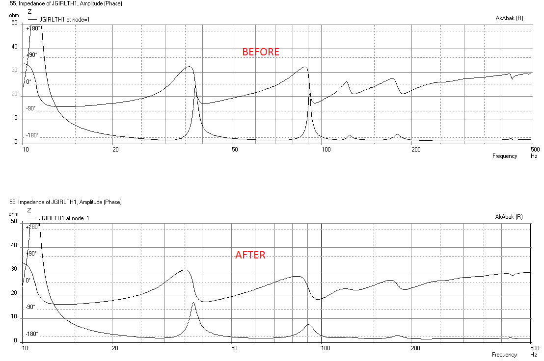
This is also a good opportunity to explain why the acoustic center is so important when using dual or multiple drivers to define S2 in offset driver designs.
In any offset driver design (including tapped horns) the part from S1 to S2 is actually working as a 1/4 wave trap. The sound enters the flare at S2, travels back to S1 and is reflected back to S2 where it creates a notch determined in frequency by the shape of the stub and the distance traveled, and in depth determined by it's size.
Here's a picture of a transmission line. The only difference in these two images is the top response sim was run as Nd and the bottom was run as Od, L12 in both is 33 cm. In the Od sim the volume defined as S1 - S2 is acting as a 1/4 wave trap because of the reflection from the closed end of the line.
This big notch is why it's important to make sure S2 is defined as the acoustic center in the case of dual or multiple drivers. If S2 is set anywhere other than the acoustic center of the drivers the notch won't be in the right place in the sim.
This also shows that 1/4 wave stubs can be very effective in creating notches if they are big enough.
In any offset driver design (including tapped horns) the part from S1 to S2 is actually working as a 1/4 wave trap. The sound enters the flare at S2, travels back to S1 and is reflected back to S2 where it creates a notch determined in frequency by the shape of the stub and the distance traveled, and in depth determined by it's size.
Here's a picture of a transmission line. The only difference in these two images is the top response sim was run as Nd and the bottom was run as Od, L12 in both is 33 cm. In the Od sim the volume defined as S1 - S2 is acting as a 1/4 wave trap because of the reflection from the closed end of the line.
An externally hosted image should be here but it was not working when we last tested it.
This big notch is why it's important to make sure S2 is defined as the acoustic center in the case of dual or multiple drivers. If S2 is set anywhere other than the acoustic center of the drivers the notch won't be in the right place in the sim.
This also shows that 1/4 wave stubs can be very effective in creating notches if they are big enough.
Last edited:

- Status
- This old topic is closed. If you want to reopen this topic, contact a moderator using the "Report Post" button.
- Home
- Loudspeakers
- Subwoofers
- FaitalPRO 15HP1060 vs 3015LF for tapped horn?