I started another thread with some better drawings, your input in simulation will be much appreciated.Sure, I can see if I can sim your design. Your sketch is a little rough on the eyes though. Do you have a better sketch with clear dimensions?
http://www.diyaudio.com/forums/multi-way/262838-synergy-tripp-10-a.html#post4077020
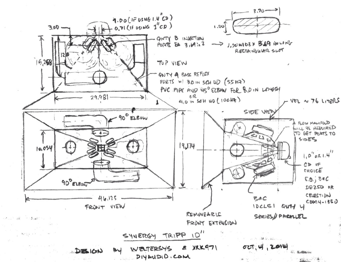
The secondary portion of the horn has not been drawn in, but would just be the usual as suggested in Bwaslo's Synergy designer.
Thanks!
Art
Sorry for the delay in response y'all. Just got wind that my warehouse space is needing to relocate, and I had to take the rest of the day to work some of that out. You know, life stuff. Blah.
Probably be back on the top hunt tomorrow. TB- that synergy horn looks like it could work! What do you mean by BP6 though?
Probably be back on the top hunt tomorrow. TB- that synergy horn looks like it could work! What do you mean by BP6 though?
Using 8FE200 4ohm specs, Oliver's spreadsheet config (S1-S4) as well as his CH inputs (VTC & ATC), and xrk's descriptors of port area & length (AP1 & LPT), I have a hornresp simulation that looks strikingly similar to xrk's work in #369. Did I get close to simulating this in hornresp?


Thanks for all the help and suggestions! As you can see I just couldn't wait until tomorrow to start simming")
Thanks for all the help and suggestions! As you can see I just couldn't wait until tomorrow to start simming
Also forgot to mention, I am using a JL HD600/1 to drive the top which can supply:

Ideally I would like to run one 8FE200 per L/R of one bank @ up to 24.5V each (let's say front bank) and the CD bridged on the rear bank attenuated way the heck down...
However, I would also have the option of bridging and running the hd600 as 2ch, which would allow me 34.6V per 8FE200- I would just need another amp to drive the CD.
The rated RMS power handling for the 8FE200 is only 130W, so it seems to me that bridging and running them at 34.6V (300W @ 4ohm) is out of the question.
My sim above is at 34.6V spread across two 8FE200's, 150W per driver (or equivalent to 24.5V each)
Last edited:
Here is that same sim with excursion limiting HPF applied

Obviously some room for improvement
And of course I also feel like I've probably done something wrong with the simulation. Chamber volume seems way too low, as well as total port area.
Another sim


Hopefully you are not facepalming too hard. I still have some learning with synergy's- gotta start somewhere! I am also not opposed to using the 10" 10CL51, I have those on hand as well- mounted in an older project
Obviously some room for improvement
And of course I also feel like I've probably done something wrong with the simulation. Chamber volume seems way too low, as well as total port area.
Another sim
Hopefully you are not facepalming too hard. I still have some learning with synergy's- gotta start somewhere! I am also not opposed to using the 10" 10CL51, I have those on hand as well- mounted in an older project
Last edited:
Using 8FE200 4ohm specs, Oliver's spreadsheet config (S1-S4) as well as his CH inputs (VTC & ATC), and xrk's descriptors of port area & length (AP1 & LPT), I have a hornresp simulation that looks strikingly similar to xrk's work in #369. Did I get close to simulating this in hornresp?
Thanks for all the help and suggestions! As you can see I just couldn't wait until tomorrow to start simming
JG,
You nailed the sim right on it appears. Looks like you can simulate a synergy now if you wanted to. Are you implementing a rear chamber with vent? Note that to get the volume of the front driver chamber small you will need a negative image plug to fill the volume in the cone like I described. Not a problem for someone with a 3d printer or a lathe.
Last edited:
Hi Jennygirl,
Post #402: "...What do you mean by BP6..."
6th order bandpass:
What's smaller than a fridge and bigger than a washing machine?
You can use this to get a quick and easy idea of the low end SPL capability of a driver for synergy horn use. The lower end will not be as heavily influenced by the horn as the upper end. See above link for an example of a BP6 design; basically the driver is mounted in the dividing wall between two vented/tuned cavities, all the output comes from the two ports. In the case of a synergy horn the smaller chamber is the throat chamber coupled to the horn, and the larger chamber is the back chamber ducted somewhere close to the horn mouth. If you build the back chamber closed you have a horn-loaded BP4, 4th order bandpass. Here is Brian Steele's page on that subject:
The Subwoofer DIY Page - 4th Order Bandpass Systems
(His site is required reading: The Subwoofer DIY Page .)
It's helpful to take a quick look at a drivers capabilities, in the case of the synergy horns you'll end up in AkAbak sooner or later.
We are using the term synergy horn loosely, more like a descriptive term. There are some patents/applications that describe the technology quite well: US 6,411,718 B1 (unity horn) - US 2009/0136072 A1 and US2006/022032 (synergy horn).
xrk971 can help you w/ the AkAbak simulations, for a programmer AkAbak should feel like a natural environment. It just doesn't have the nice Wizards and Schematics as Hornresp.
Regards,
Last edited:
Jennygirl,Hopefully you are not facepalming too hard. I still have some learning with synergy's- gotta start somewhere! I am also not opposed to using the 10" 10CL51, I have those on hand as well- mounted in an older project
To figure the throat chamber size (ATC), it is necessary to accurately measure the volume the cone itself takes up, since a difference of as little as 50 cc can make a difference. This can be done by putting some thin plastic wrap over the cone and filling it up with water up to the gasket, then pouring the water into a measuring cup(s). Your 8" might be as little as 125cc, while the 10CL51 may be 2-4 times that. A cross sectional drawing of the cone is also useful to determine the shape needed to reduce ATC, if needed.
Gasket depth is usually not deep enough to prevent the outer perimeter of the cone from striking the baffle at Xmax or Xlim, so a ring around that area must be routed out, which increases ATC slightly. An example of the ring below, and a phase plug conforming to the cone shape. Offset drivers would need the plug to be circular.
Could you please measure the 10CL51 cone volume?
Thanks,
Art
Attachments


Last edited:
Thanks Oliver and xrk- that info helps and I'm glad I'm indeed on the right track! That makes me super happy to hear!
Welter, I will be happy to do that for you. I don't really have an accurate method of measuring volume, though..
One of my roommates does have a decent scale (I believe down to 1/10th of a gram), could I just zero the driver on the scale and pour the water in to get the total weight- figure out volume via mass & density?
All you need is a measuring cup as found in any kitchen, most are labeled in ML, same as CC, 1000 ML or CC to a liter.Welter, I will be happy to do that for you. I don't really have an accurate method of measuring volume, though..
The 10CL51 is 847.78cc. I filled it all the way up to the foam seal with fine white rice and then leveled it off with a straightedge. Then, I dumped it into a large pan and using an accurate looking set of measuring cups (1/2cup, then a tablespoon measuring cup, and a teaspoon cup) I got 7 half cups, 1tbsp, and 1tsp.
7 half cups = 3.5 cups = 847.78cc
1tbsp = 14.79cc
1tsp = 4.93cc
total 847.78cc
7 half cups = 3.5 cups = 847.78cc
1tbsp = 14.79cc
1tsp = 4.93cc
total 847.78cc
I think I am set on using the 10CL51 for the synergy, by the way. I am getting the picture that there are too many low frequency limitations of the 8FE200. Plus, my 10CL51's are already broken in!
And with the minimum height being >10" anyway, I might as well. They are more sensitive and have a higher xmax
And with the minimum height being >10" anyway, I might as well. They are more sensitive and have a higher xmax
The 10CL51 is 847.78cc. I filled it all the way up to the foam seal with fine white rice and then leveled it off with a straightedge. Then, I dumped it into a large pan and using an accurate looking set of measuring cups (1/2cup, then a tablespoon measuring cup, and a teaspoon cup) I got 7 half cups, 1tbsp, and 1tsp.
7 half cups = 3.5 cups = 847.78cc
1tbsp = 14.79cc
1tsp = 4.93cc
total 847.78cc
Thanks, JG! 850cc is close enough for me. I really underestimated it so it looks like Weltersys will need to put a form inside RJ yaks up the volume.
10CL51 sim for synergy


No acoustic effect on filter necessary to show because it hits 6mm xmax right on the money!
You should check out the design that Weltersys and I are working on. It can be 30 wide x 10 high x 18 deep in compact form.
http://www.diyaudio.com/forums/multi-way/262838-synergy-tripp-10-a-2.html#post4078170
I am super interested and impressed with your guys' project, I think you are going for a full range with sub 100hz capability?
I am seemingly getting some great results with 4x 10CL51 sealed at 34.64V (300W @ 4ohm) in your compact version for my needs (100hz+). I reduced chamber volume quite considerably to increase tuning. 4x 10CL51 weighs the same as two 8FE200's and I get that voltage driving the 4 10's off of 2ch of my JL 4ch 600W amp (2x 10CL @ 4ohm at 150W per channel). The other 2ch remain to drive the HF144, which simplifies things.
Clearly this is the best I've seen so far in terms of efficiency, and after watching several synergy videos on youtube (including DSL's video) I am undeniably convinced on the topic of sound quality.
Here is my most recent sim. S1-S4 and L12, L23, L34 have been copied from your AWtop1-dims.pdf attachment here. Also I am simming in 4pi space to be on the safe side.


comparison between 2pi and 4pi (2pi in red)

wow
I am seemingly getting some great results with 4x 10CL51 sealed at 34.64V (300W @ 4ohm) in your compact version for my needs (100hz+). I reduced chamber volume quite considerably to increase tuning. 4x 10CL51 weighs the same as two 8FE200's and I get that voltage driving the 4 10's off of 2ch of my JL 4ch 600W amp (2x 10CL @ 4ohm at 150W per channel). The other 2ch remain to drive the HF144, which simplifies things.
Clearly this is the best I've seen so far in terms of efficiency, and after watching several synergy videos on youtube (including DSL's video) I am undeniably convinced on the topic of sound quality.
Here is my most recent sim. S1-S4 and L12, L23, L34 have been copied from your AWtop1-dims.pdf attachment here. Also I am simming in 4pi space to be on the safe side.
comparison between 2pi and 4pi (2pi in red)
wow
Last edited:
I just realized I may be a bit confused about simulating voltages using separate channels..
If I have 2ch at 24.5V (150W @ 4 ohm each) coming from the amp, does that mean I can sim at 34.64V (300W @ 4ohm total) for the combined power? It's not really making sense to me that way, brain is fighting me on it thinking the voltage would simply stay the same 24.5v in the sim (and by combining it would essentially become 300W @ 2ohm total)
Thank you
Last edited:
I just realized I may be a bit confused about simulating voltages using separate channels..
If I have 2ch at 24.5V (150W @ 4 ohm each) coming from the amp, does that mean I can sim at 34.64V (300W @ 4ohm total) for the combined power? It's not really making sense to me that way, brain is fighting me on it thinking the voltage would simply stay the same 24.5v in the sim (and by combining it would essentially become 300W @ 2ohm total)
Thank you
I guess it depends on how the drivers are wired. If you are asking how to get equivalent SPL based on the fact that you will use multiple units of the same horn, just keep the total power delivered equivalent. So I think you have it right. But in reality, the xmax may be exceeded for that one driver being asked to simulate multiple drivers. Doesn't HR have a utility to simulate multiple speaker units?
Btw, the design for the synergy is sketched out in the other thread: http://www.diyaudio.com/forums/multi-way/262838-synergy-tripp-10-a.html#post4077489
and shown here also:
- Home
- Loudspeakers
- Subwoofers
- FaitalPRO 15HP1060 vs 3015LF for tapped horn?