That sawtooth is the output from the buffer, while the sinewave below is its input? What am I missing?
You don't have to use such huge caps, btw. Use X7R for best results. Small foil caps like WIMA MKS2 will do just fine, too. Best is to make the leads as short as possible, ie. place the cap on the bottom of the board and solder it right between the pins of the socket. Please try this with the buffer, too. A buffer should not produce a sawtooth, output should look like input...
EDIT: Guess I got the scope shots confused. But still, that "sea" wave looks strange and seems to be present at the input already.
On the scope screens, the bottom wave is the input wave always, the top of the first is at the output of the 713s, both L/R identical but only one channel pictured. The second picture top wave is the output at the buffer, which looks good.
OK, I am translating and digesting you all's comments.
Last edited:
...
A further alternative:
Provide both AC and DC inputs at the input.
The DC input socket would have no coupling capacitor.
The other input socket would have the capacitor.
As far as I have seen, every opamp datasheet specifies decoupling capacitors.
Each manufacturer specifies a mix of MF and HF decoupling, some on both power pins to power ground, some between the power pins, some from one power pin to power ground.
Initially you MUST follow the manufacturers advice. With experience (sometimes from others) you may decide to vary the decoupling to slightly different from the manufacturer specified values and types. Many manufacturers specify Tantalum caps for the MF decoupling. This Forum tend to shy away from Tantalum.
I used to use Tantalum, then I stopped, recently I have started again but at <50% of voltage rating and where impulsive interference cannot damage the cap.
If I don't succeed at eliminating the bit of hum left at the sound, I may try that. Yes, the 49713 application notes speak of Tantalum caps. See attached.
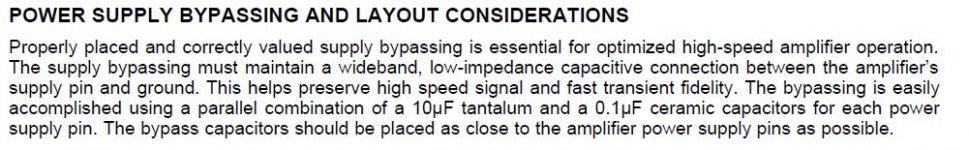
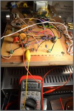
Took care of the .1 uF cap across the 49713 power pins as recommended earlier. Yes, I know the caps are big, but they are recycled from an old scope.
... Small foil caps like WIMA MKS2 will do just fine, too. Best is to make the leads as short as possible, ie. place the cap on the bottom of the board and solder it right between the pins of the socket. Please try this with the buffer, too...
Will try shorter leads...
...You will need a good ground plane implementation to keep it stable. Possibly surface mount .01 uF MLCC at each power supply pin.
Next "to do" is to bypass the power supply pins, see attached from the LME49713 Datasheet Application Notes.
Attachments
Small foil caps like WIMA MKS2 will do just fine,
Possibly surface mount .01 uF MLCC
These are not all the same.a 0.1uF ceramic...as close to the amplifier power supply pins as possible
The Wima MKS2 will not do the job !
The extract also says
The "ground" referred to is Power Ground. The ground side connection from the capacitors MUST also be "wideband, low impedance capacitive connection".a wideband, low-impedance capacitive connection between the amplifier's supply pin and ground.
These are not all the same.
The Wima MKS2 will not do the job !
Correct, Andrew. If Wima, I'd go for FKC or FKP02/2/3.
However, 33 nF to 100 nF is a good starting point.
")
Linkwitz uses the OPA2134 dual opamps in all of his analog circuitry. Because I highly respect his tech abilities I have been using those in all of my high end Hi-Fi projects for years with no problems and excellent sound. Although some other opamps may have better specs on paper, I believe that any audible difference is way more about the circuit than the opamp. Faster opamps are more likely to oscillate unless you really know what you're doing. Trying to find an opamp better than the OPA2134 for high end audio is IMO a waste of time.
Linkwitz uses the OPA2134 dual opamps in all of his analog circuitry. Because I highly respect his tech abilities I have been using those in all of my high end Hi-Fi projects for years with no problems and excellent sound. Although some other opamps may have better specs on paper, I believe that any audible difference is way more about the circuit than the opamp. Faster opamps are more likely to oscillate unless you really know what you're doing. Trying to find an opamp better than the OPA2134 for high end audio is IMO a waste of time.
I agree fully, have used a lot of 134s. Now on to lm4562, which is also nice, but much more temperamental. It excels at pick up radio waves, just to give an example. And I can't really tell if they are that much better.
OPA 1641 is better.
When you like the OPA2134 you like distortion, at least in the treble and when not care is taken for common mode distortion.
Douglas Self was not amused about this opamp.
Groner also found problems.
The distortion is low enough though to be not audible.
But that is true since 40years where the NE5534 came out.
...
As far as I have seen, every opamp datasheet specifies decoupling capacitors.
Each manufacturer specifies a mix of MF and HF decoupling, some on both power pins to power ground, some between the power pins, some from one power pin to power ground.
Initially you MUST follow the manufacturers advice. With experience (sometimes from others) you may decide to vary the decoupling to slightly different from the manufacturer specified values and types. Many manufacturers specify Tantalum caps for the MF decoupling. This Forum tend to shy away from Tantalum.
I used to use Tantalum, then I stopped, recently I have started again but at <50% of voltage rating and where impulsive interference cannot damage the cap.
Decoupling per the manufacturer recommendation was the last and missing key in this whole thing. The op amps were oscillating until the decoupling was done.
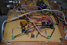
I used a .01 uF ceramic capacitor to ground off each power pin on each op amp and a 33 uF electrolytic on each rail to ground (did not have .1 uF ceramic, but a bunch of other film types and I wanted the low ESR of the ceramics).
Was not ready for how much difference this would make, no more hum, no hiss and static when the op amps started to oscillate, and the op amps cases are no longer hot to the touch as before.
The sound of the LME49713 is beyond any of the popular and friendly op amps as the OPA2134--which I use often, perhaps twice as good (IMLO) and worth the effort. Glad for it and you all's help.
I am listening to the pre now, I will be moving it to a case.
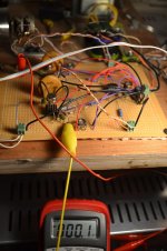
Attached you can see the offset output (0.1 and 0.0 mV) of the preamp, right channel, then left quite good!
Now, how do I get a PCB made for this, I don't want to end with another wiry mess

Thanks.
Attachments
Last edited:
Tantalum caps are higher distortion and lower reliability, so I never use them. Power supply bypass cap values aren't critical at all. What is critical is that the small value caps (.01, .1 whatever) need to be within an inch of each opamp; that's my "rule of thumb" for audio circuits anyway. For Rf circuitry or switch mode poweramps you'd want the caps to be right at the chip.
I'll always put a bigger cap; an aluminum electrolytic of maybe 10uF - 100uF on each board for low power circuits, and 100uF - 1kuf for power amp circuits (with a separate ground return to the star center ground point of the chassis), besides the much bigger caps in the power supply circuit itself.
Another important thing is to put a 100 - 200 ohm R in series with the output of any opamp (outside of the feedback loop) to minimize the effect of the load reactance messing with the phase margin of the opamp circuit. I also always put a passive Rf filter in front of any opamp circuit as a whole (for signals entering the chassis), so I don't ask the opamps to do something they can't do well. I usually set that at about 160kHZ (maybe a 1K R in series and a 1nF cap to gnd.). A cap is also usually placed across the feedback resistor to further optimize the phase margin; the lower the "dominant pole", the better the phase margin, in a typical circuit. I'll usually set that to about 200kHZ unless I have a reason to do otherwise. I use ceramic caps for PS bypass and polypropylene or polystyrene for all other caps if possible. Then you have a great circuit.
These tips will make a much bigger improvement in circuit operation than the difference between an OPA2134 and any opamp that anyone thinks is better. Not using these techniques properly is IMO why many people think they hear a difference in opamps that are better than an OPA2134. They may have intermittent or spurious oscillations occurring with some opamps and not others, and not realize it. Also slewing or detection of Rf energies when at very high frequencies the opamp becomes non-linear. The 5534 opamp is also great sounding, but has a bipolar input circuit so isn't as high an impedance, which could be an issue in some circuits.
I've had boards made by expresspcb.com but they aren't real cheap. The free layout software is nice enough.
Last edited:
... I also always put a passive Rf filter in front of any opamp circuit as a whole (for signals entering the chassis), so I don't ask the opamps to do something they can't do well. I usually set that at about 160kHZ (maybe a 1K R in series and a 1nF cap to gnd.).
A cap is also usually placed across the feedback resistor to further optimize the phase margin; the lower the "dominant pole", the better the phase margin, in a typical circuit. I'll usually set that to about 200kHZ unless I have a reason to do otherwise. I use ceramic caps for PS bypass and polypropylene or polystyrene for all other caps if possible. Then you have a great circuit.
...
Thanks Bob for the good comments. Can you expand on the first paragraph above, do you mean an RC network at each signal input into the board to filter signals above 160kHZ?
Also, specifically for this op amp and maybe other CFB op amps, the cap across the feedback resistor is discouraged. See footnote attached taken from the LME49713 app. notes.
Thanks again.
Attachments
Yea, I was only talking about voltage feedback opamps. Current FB opamps appear to be optimized for much faster speeds, for digital data processing or something. I haven't spent much time looking at those and haven't used any.Thanks Bob for the good comments. Can you expand on the first paragraph above, do you mean an RC network at each signal input into the board to filter signals above 160kHZ?
Also, specifically for this op amp and maybe other CFB op amps, the cap across the feedback resistor is discouraged. See footnote attached taken from the LME49713 app. notes.
Thanks again.
Not sure what part of the first paragraph you were asking about.
At high frequencies, the wire going to and from a cap becomes a significant inductor, which causes phase shift, and can cause circuits to oscillate or ring at very high frequencies, which often includes slewing and all the distortion byproducts of that.
Having the separate ground return wire for the big caps on a non-power supply board reduces hum induced by the caps charging current modulating the board ground relative to the chassis ground, which is the star center common ground point for all grounds in the chassis. Since you've also got the 0.1uF (or so) ceramic caps bypassing the PS right at he chips, the inductance of the long wires on the big caps aren't a problem. I generally only bother to have this second ground return wire on power amp boards where the cap is pretty big. Maybe I should on low power boards too (?). You always want the opamp to see zero ohms from 0.1HZ to infra-red when it looks at the power supply. Any deviation from this makes phase margin more questionable and complicated.
The Wima MKS2 will not do the job !
Okay okay, strike them from the list
.I've already used them successfully for this purpose and saw them used in commercial equipment, too. Better than no cap at all, I guess, but then again don't use them if you have ceramics handy
.Linkwitz uses the OPA2134 dual opamps in all of his analog circuitry. Because I highly respect his tech abilities I have been using those in all of my high end Hi-Fi projects for years with no problems and excellent sound. Although some other opamps may have better specs on paper, I believe that any audible difference is way more about the circuit than the opamp. Faster opamps are more likely to oscillate unless you really know what you're doing. Trying to find an opamp better than the OPA2134 for high end audio is IMO a waste of time.
I like OPA2134s and OPA604 op amps as well. In general, I tend to prefer amps with JFET inputs, either integrated or discrete. Common mode distortion is measurably a bit higher than for BJT op amps, but is still very low, and is low-order.
Extra inductance in power supply wiring can always be problematic due to its inductance, even sometimes with ceramic bypassing right at the pins of all of the ICs. Sometimes a resonance with moderate to high Q can be formed between the wiring inductance and the low-ESR bypass capacitors. In such cases, placement of a few elctrolytics in parallel here and there can kill the Q of the resonance with their lossy ESR. A 0.1 ceramic in parallel with a 10uF electrolytic can be very effective.
Cheers,
Bob
You like OPA2134 and OPA604.
For the sound or for the measurements ?
That whould surprise me. Both.
How do they sound ?
I do not hope warm.
Then we are again in a hopeless, neverending discussion about subjective sound.
Hey, many like the sound of the JLH 10W Class A on 10cm wideband drivers.
" When we are going out of busyness everything most go " Steely Dan.
Yes, JFet input is more robust for RF ingress, here i agree.
BUT....
...I also always put a passive Rf filter in front of any opamp circuit as a whole (for signals entering the chassis), so I don't ask the opamps to do something they can't do well. I usually set that at about 160kHZ (maybe a 1K R in series and a 1nF cap to gnd.)...
This is of interest, can you explain a bit?
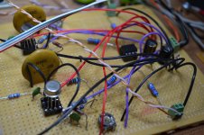
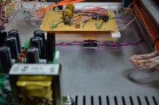
For tonight's progress, off the wood board unto the chassis. Sound is quite clean...tomorrow tie down the wires.
Attachments
How does it measure ?
Sorry, this question is a tradition here.
In engineering, it is about the stupidest question you can pose
How does it measure ?
Sorry, this question is a tradition here.
I hope to put it on the scope tonight and see how the waves look and will post those pics. Also, output offset is rock steady and I can get it to 0.0 VDC quite easy. What else should I measure? I am limited to the Tektronix scope and the multimeter.
Rolling off the frequency response using a cap across the feedback resistor depends on the opamps ability to cleanly operate well above the frequency you want the rolloff at. But the feedback itself is rolling off as you go up in frequency, so by the time you get up to several hundred kHZ, because the feedback has become small, the opamp may not be very distortion free, so it acts like an AM radio detector and generates sum and difference frequencies based on whatever Rf energy is coming in. The feedback necessarily rolls off (even without the cap added) because you need a "dominant pole" well ahead of any other rollofff poles in order to have good phase margin. A dominant pole appears to be designed into all opamps. Look at the open loop F response graph.This is of interest, can you explain a bit?
So a much better way to dump Rf energy coming in is with a passive Rf filter ahead of the opamp circuit, which is just an R in series and a cap to ground. A true nerd might also put ferrite beads on the incoming wire so then it's an inductor in series and a cap to ground. A 2 pole filter instead of one pole. I don't bother with the beads (maybe I should).
To design this filter you need to have some idea what the source impedance will be. If your source takes a signal from the plate of a tube, you can be way off on this, but virtually all other sources I know of will have an output impedance of less than 1kohm, so I design for that. Since series resistors can add hiss noise I prefer to keep the series resistor small. I usually go with 1k, which adds to the 1K source impedance from the point of view of the cap to ground after the R. So then you just calculate a cap based on 2kohms. Whatever input impedance to ground resistance the opamp circuit will have will create a "zero", which cancels the rolloff, so you want that to be as high as is practical. For a one pole RC passive filter the math is:
C = 1/ (2 times pie times F times R as seen by the cap)
Example: C = 1/ (6.283 x 100kHZ x 2kohms) = 796pF
So then you choose the nearest standard value which in this case is either 820pF (rare but I think they exist) or 1nF (very common).
If you choose 1nF, the actual -3dB point will be :
F = 1/ (2 pie x 1nF x 2Kohm) = 80kHZ
If the R to ground off the + input of the opamp (which this feeds) is 50Kohm or higher, this filter will be pretty effective. It would be more effective if this 50K was 1Mohm, but then you've got a 1mohm R making hiss noise. I usually use 50K there and believe it to be a good tradeoff.
This Rf filter is for signals coming into the chassis. I don't put one of these on each stage within a given chassis.
A series R at the final output of a preamp circuit, for example (usually 100 - 200 ohms) will make the opamp more stable (very important), and also form an RLC filter with the interconnect cable that goes to the poweramps, so it's good to be aware of how much capacitance that interconnect cable will have if it's very long. It will form another passive Rf filter itself.
So a much better way to dump Rf energy coming in is with a passive Rf filter ahead of the opamp circuit, which is just an R in series and a cap to ground. A true nerd might also put ferrite beads on the incoming wire so then it's an inductor in series and a cap to ground. A 2 pole filter instead of one pole. I don't bother with the beads (maybe I should).
If the R to ground off the + input of the opamp (which this feeds) is 50Kohm or higher, this filter will be pretty effective. It would be more effective if this 50K was 1Mohm, but then you've got a 1mohm R making hiss noise. I usually use 50K there and believe it to be a good tradeoff.
Agree with most of what you write for line level, but for this para. The R off the ground to the + input in an AC coupled input stage is there to source or sink the bias current and set a reference level. Input thermal noise level is determined by the source impedance, 2 K in the example you used, regardless of the size of this R.
edit: not the whole truth either. current through this R produces excess noise, so for high values and large bias currents, use a good one.
Last edited:
- Status
- This old topic is closed. If you want to reopen this topic, contact a moderator using the "Report Post" button.
- Home
- Amplifiers
- Solid State
- National opamp inflation